CYLINDER HEAD GASKET LEAK REPAIR PROCEDURES-DIESEL

SUBJECT: CYLINDER HEAD GASKET LEAK REPAIR PROCEDURES
VEHICLES AFFECTED: 1978-79-80-81 Vehicles Equipped with 350 Diesel Engines
When cylinder head gasket replacements are being made for any reason on the 1978 through to 81 model diesel engines, it is important that the most current procedures and the latest design parts be used to correct the condition. This bulletin combines the latest diagnosis, repair and parts information for use in making a head gasket leak diagnosis or replacement on the 350 diesel engine.
OVERHEATING OR NO HEAT
An overheating or no heat from the heater condition may be caused by a compression leak in the head gasket. This will be evident by air bubbles in the coolant recovery tank. To determine which head gasket is leaking, lower the coolant level and remove the thermostat housing and the belts on the water pump. Start the engine and observe the coolant in the intake manifold to determine which side the bubbles are coming from.
CYLINDER HEADS
While the cylinder heads are off the engine they should be carefully inspected for a number of possible conditions, one of which is warpage. If any cylinder head is warped more than .010 inch it should be replaced resurfacing is not recommended. Another area of importance to check is cylinder block dowel pin to cylinder head interference. It is essential to verify that the cylinder head sits flush and squarely on the cylinder block. This is accomplished by placing the cylinder head on the block without the head gasket installed. Once this is done, run a .005 feeler gauge around the perimeter of the area where the head and the block meet. There should be zero clearance thus verifying that the head is flush with the block and there is no dowel pin interference.
The prechambers must not be recessed into the cylinder head or protrude out of the cylinder head by more than .004 inch as this will affect cylinder head gasket sealing. The sealing bead on the gasket must not allow compression gases into the water jacket. Make sure the sealing bead goes around all core holes in the block and head, if the sealing bead crosses a raised, depressed or stamped area the raised area should be filed and the depressed or stamped area filled with RTV sealer and reassembled before the RTV sealer cures.
Minor surface cracks in the valve port area of the cylinder head especially between the intake and exhaust valve ports are a normal condition. These surface cracks do not affect the function of the cylinder heads and they should not be replaced for this condition. The use of magnaflux is not recommended as cracks in the cylinder head that affect performance are readily visible to the naked eye, therefore magnafluxing is an unnecessary expense.
CYLINDER HEAD BOLTS
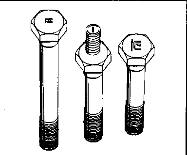
A new head bolt with increased torque capacity was introduced into production March 18, 1980 and is available from the GM Canada Parts Department. This new head bolt can be identified as shown in Fig. 1.
When removing or replacing a cylinder head for any reason on a 1978-79-80 diesel engine be sure to use the new head bolts if they have not already been installed in the engine.
Before the cylinder head is reinstalled, make sure the mounting bolt holes are tapped deep enough into the block. First, blow out any chips or liquid in the bolt holes. Then place the cylinder head on the cylinder block without the cylinder head gasket installed. Clean and lightly oil the cylinder head bolts and screw them into the block by hand to check for the proper block bolt hole depth. Having run the bolt down as far as it will go by hand, the bolt head should contact the cylinder head. This will indicate that the holes have been tapped deep enough in the block. This will allow the proper clamping load to be applied to the cylinder head gasket.
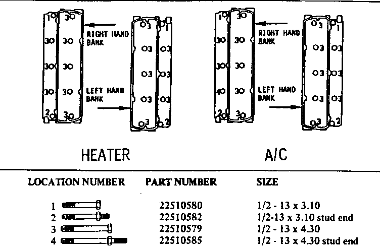
Listed in Fig. 2 is cylinder head bolt location number and part number. Refer to Fig. 2 for the location of the head bolt in the cylinder head.
Bolts should be cleaned by wire brushing the threads. Before installation, all bolts should be oiled on the threads and bottom side of the bolt head with engine oil.
TORQUE
Cylinder head bolt torque procedures used on the diesel engine should be followed closely to assure that the proper clamping load is being applied to the cylinder head gasket.
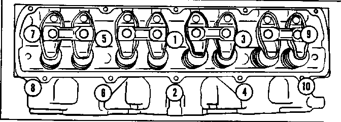
The new head bolts are to be torqued in the sequence shown in Figure 3. Bolts are to be installed and torqued to 135 N.m (100 ft. lbs.) and then retorqued to 180 N.m (130 ft. lbs. ). The use of a known accurate torque wrench is a must when following this procedure.
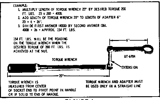
When using a torque wrench with an adapter, the reading on the torque wrench will not reflect the actual torque of the bolt due to the extra length of the combined torque wrench and adapter. To obtain the correct torque readings in these cases use the following formula: Multiply the length of the torque wrench by the number of pounds of the desired torque. Then add the length of the torque wrench to the length of the adapter. Divide the first answer by the second answer and the result will be the correct torque reading. (Fig. 4)
WATER PUMP
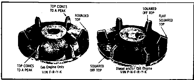
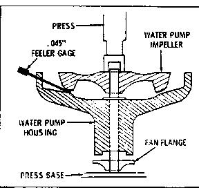
Another area that must be checked is the water pump for the proper impeller. If the water pump impeller blades have rounded edges, and tips that are peaked or pointed (Fig. 5) the water pump assembly must be replaced. Clearance on all punips should be checked between the peak of the blade and the housing, Fig. 6, and should not exceed. 045 inch. If the clearance exceeds .045 inch, press the impeller on to the shaft to obtain .045 inch clearance of less. When pressing the impeller onto the bearing shaft be sure to support the opposite end of the shaft to prevent distortion of the fan blade flange and damage to the bearing.
CYLINDER HEAD GASKETS
A new design head gasket went into production on March 17, 1981 starting with engine number D10238186.
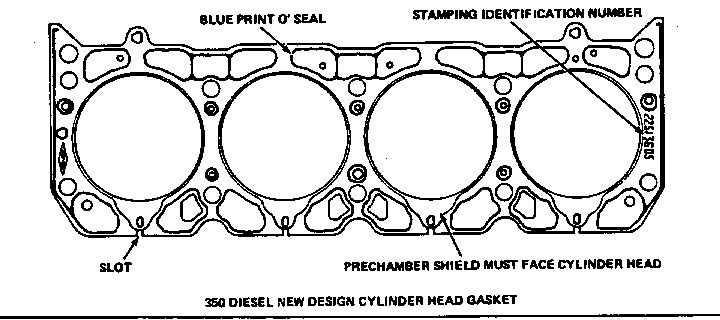
This newly designed head gasket is available for service replacement on all 1978, 79, 80, and 81 350 diesel engines and can be identified visually by the use of blue print o'seal instead of orange. This gasket is of the slotted and shimmed design and carries stamping No. 22513605 as illustrated in Fig. 7.
It must be remembered that when installing the diesel cylinder head gaskets no sealer is to be used on the gasket. On all diesel engines the prechamber shield on the head gasket (Fig. 7) must be installed towards the cylinder head. Current production provides two dowel pin locations and it is possible to install the cylinder head gasket upside down.
The following list contains the most updated diesel engine gasket kit part numbers. which contain the new head gasket and their application:
YEAR PART NUMBER PART NAME ---- ----------- --------- 78-79-80-81 22513605 Head Gasket
1981 22514844 Valve Grind Gasket Kit with internal EGR
1981 22514845 Valve Grind Gasket Kit with external EGR
*78-79-80 22514845 Valve Grind Gasket Kit
1981 22514842 Engine Overhaul Gasket Kit with internal EGR
1981 22514843 Engine Overhaul Gasket Kit with external EGR
*78-79-80 22514843 Engine Overhaul Gasket Kit
* Also 1981 Engines without EGR.
DIESEL HEAD GASKET
We have received reports indicating head gasket failures on diesel engines which had the new head gaskets installed, part number 22513605. On further investigation of each report, several different possible conditions were discovered, I.E., Head bolts were not cleaned and oiled before reinstallation in block, prechambers protruding above surface of cylinder head, burrs on cylinder head, dirt or rust in cylinder head bolt holes, or head gaskets were sprayed with a copper-coat sealer. It was determined through investigation that the head gaskets did not fail due to the product, but rather had been installed improperly without following the procedures in bulletin 81-T-5.
LEAKING CYLINDER HEAD GASKET - DIESEL ENGINES
Questions regarding recessed or protruding prechambers in the cylinder head have been raised. Dealer technical bulletin 81-T-5 states that prechambers must not be recessed into the cylinder head or protrude out of the cylinder head by more than .004". This measurement should be made on both sides of the prechamber where the gasket sealing ring crosses the prechamber and cylinder head. It does not matter if the prechamber is cocked a little bit so that you get a different measurement on each side. Both sides, however, must be with- in the tolerance.
General Motors bulletins are intended for use by professional technicians, not a "do-it-yourselfer". They are written to inform those technicians of conditions that may occur on some vehicles, or to provide information that could assist in the proper service of a vehicle. Properly trained technicians have the equipment, tools, safety instructions and know-how to do a job properly and safely. If a condition is described, do not assume that the bulletin applies to your vehicle, or that your vehicle will have that condition. See a General Motors dealer servicing your brand of General Motors vehicle for information on whether your vehicle may benefit from the information.
