For 1990-2009 cars only
Ball Joint Inspection Front Suspension
Special Tools
J 8001 Dial Indicator Set
- Raise and suitably support the vehicle. Refer to Lifting and Jacking the Vehicle .
- Remove the front tire and wheel assemblies. Refer to Tire and Wheel Removal and Installation .
- Perform a visual inspection of the ball joint seals for cuts or tears. If damage exists, replace the ball joint. Refer to Lower Control Arm Ball Joint Replacement .
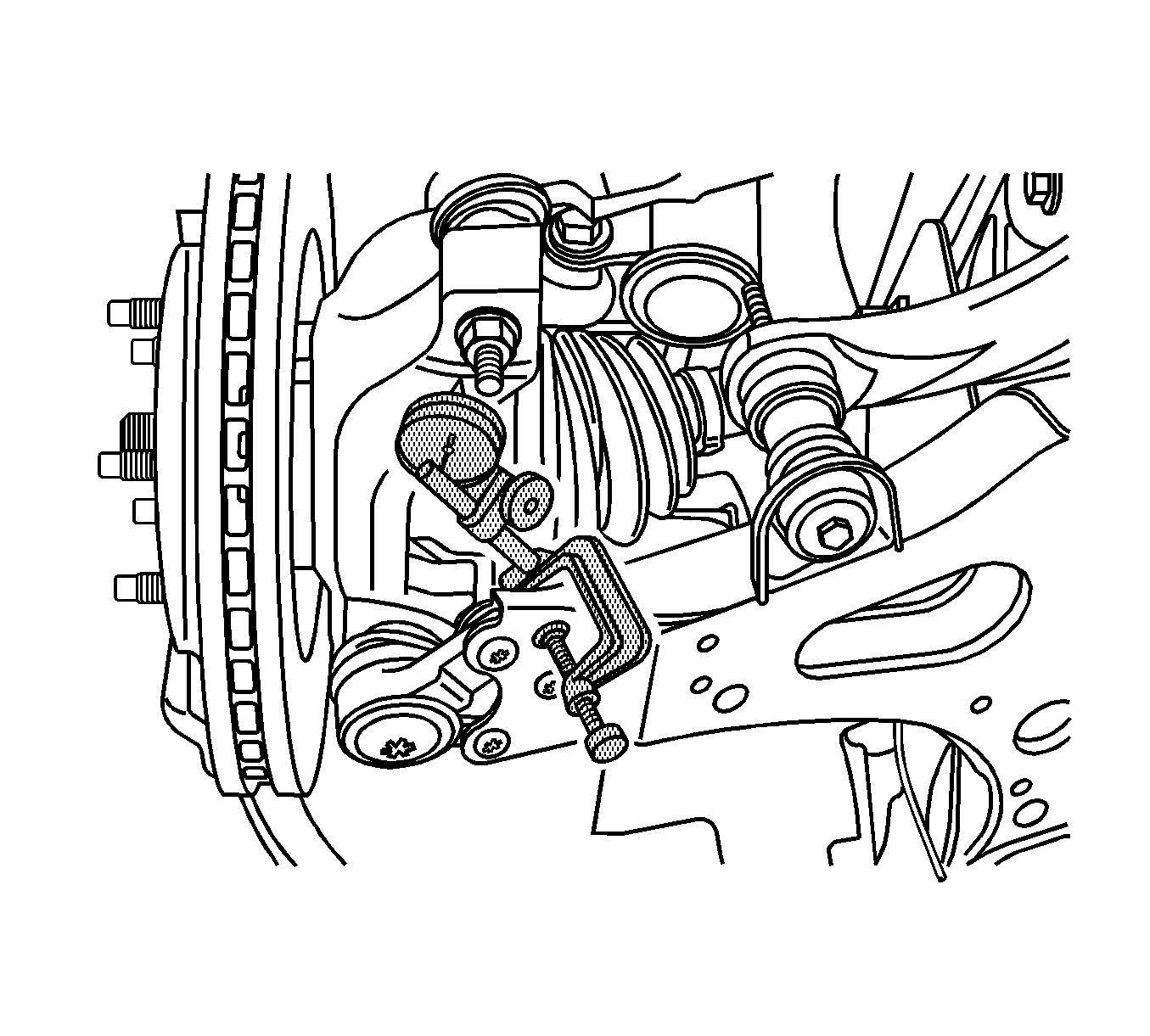
- Position J 8001 onto the lower control arm with the needle on the steering knuckle as shown. Set the dial indicator to zero.
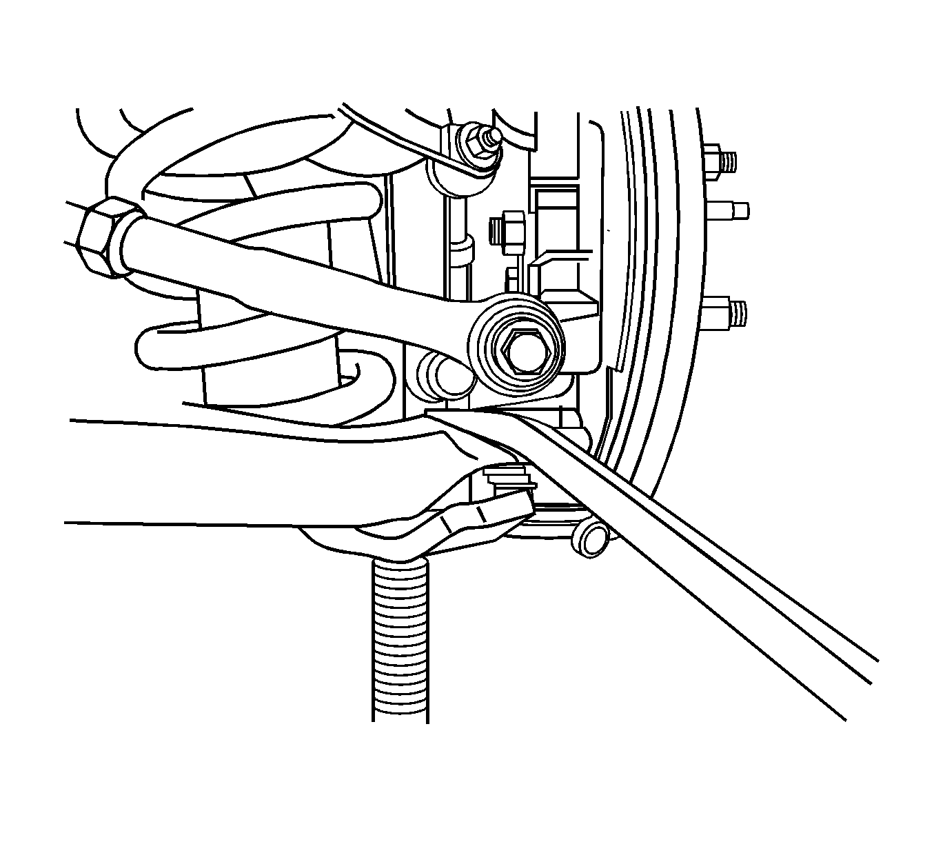
- Position a pry bar, lift the steering knuckle upward, then let it settle while observing the dial indicator. The reading should be within 0.7 mm (0.028 in) specification. If the ball joint is out of specification, replace the ball joint. Refer to Lower Control Arm Ball Joint Replacement .

Important: Do not pry between the lower control arm and the wheel drive shaft boot.
Ball Joint Inspection Rear Suspension - IRS
- Raise and suitably support the vehicle. Refer to Lifting and Jacking the Vehicle .
- Remove the rear tire and wheel assemblies. Refer to Tire and Wheel Removal and Installation .
- Perform a visual inspection of the ball joint seals for cuts or tears. If damage exists, replace the ball joint. Refer to Lower Control Arm Ball Joint Replacement .
- Check wheel bearing for looseness. Refer to Wheel Bearings Diagnosis .
- Remove the spring force from the lower control arm by supporting the lower control arm with a floor stand.
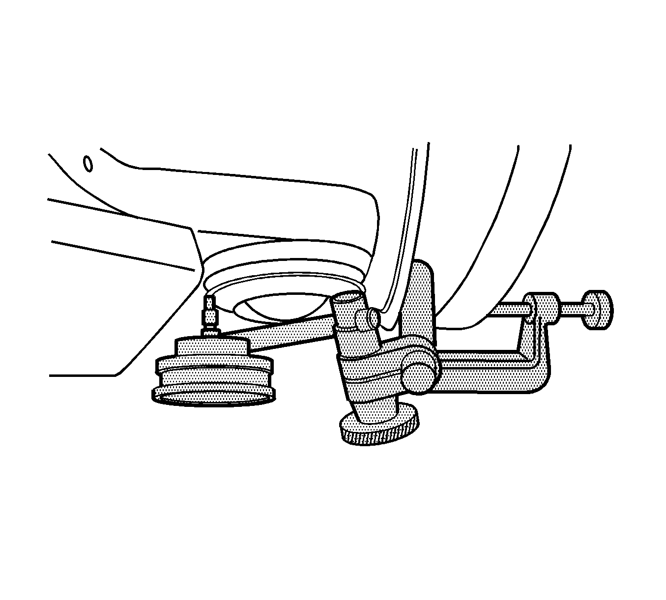
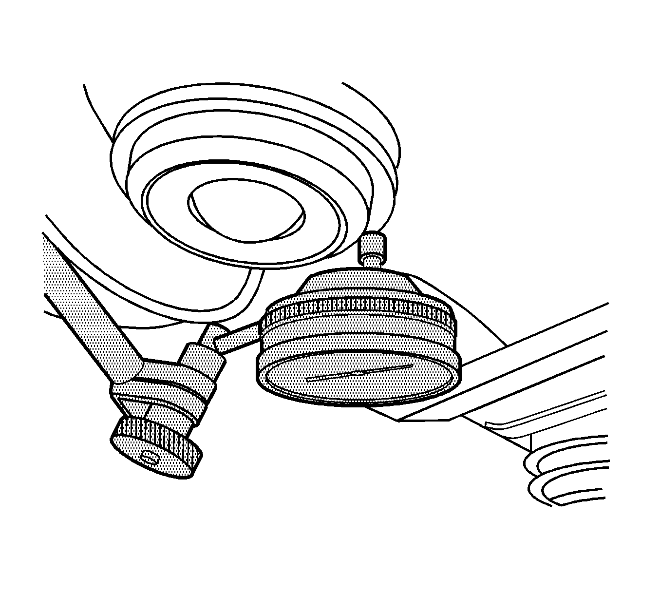
- Clamp the J 8001 Dial Indicator, to the bottom of the brake rotor. Place the dial indicator needle against the flange of the ball joint at the ball joint centerline most inboard point.
- Set the dial indicator to zero.
- Position a pry bar between the outer tie end-arm of the knuckle and the lower control arm. Lift the steering knuckle upward, then let it settle while observing the dial indicator. If the reading is 0.5 mm (0.020 in) or more, replace the ball joint. Refer to Lower Control Arm Ball Joint Replacement .
Position the floor stand as far outboard as possible and raise the control arm 75 mm (3 in).

Important: If rotor does not have a hold down bolt, install 3 lug nuts to ensure the stability of the rotor.


Important: Do NOT pry between the lower control arm and the wheel drive shaft boot or damage may result. Do NOT pry on the knuckle boss near the ball joint boot or damage to the ball joint may result.
