Tools Required
J 7872 Dial Indicator Set
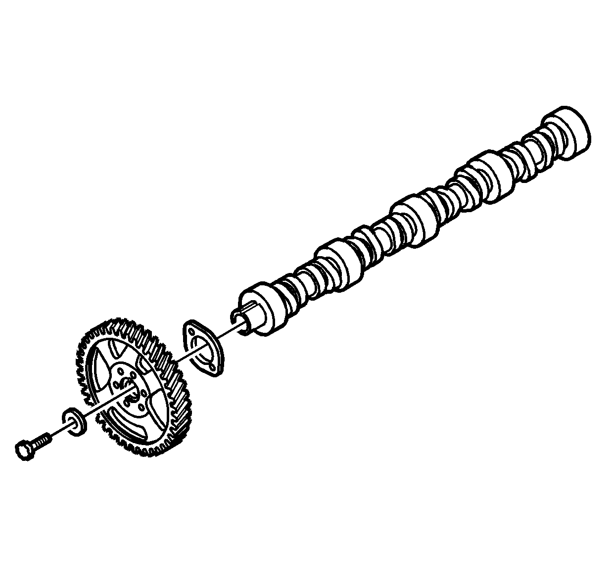
- Install the camshaft thrust plate to the camshaft.
- Install the camshaft driven gear.
- Install a new camshaft driven gear bolt.
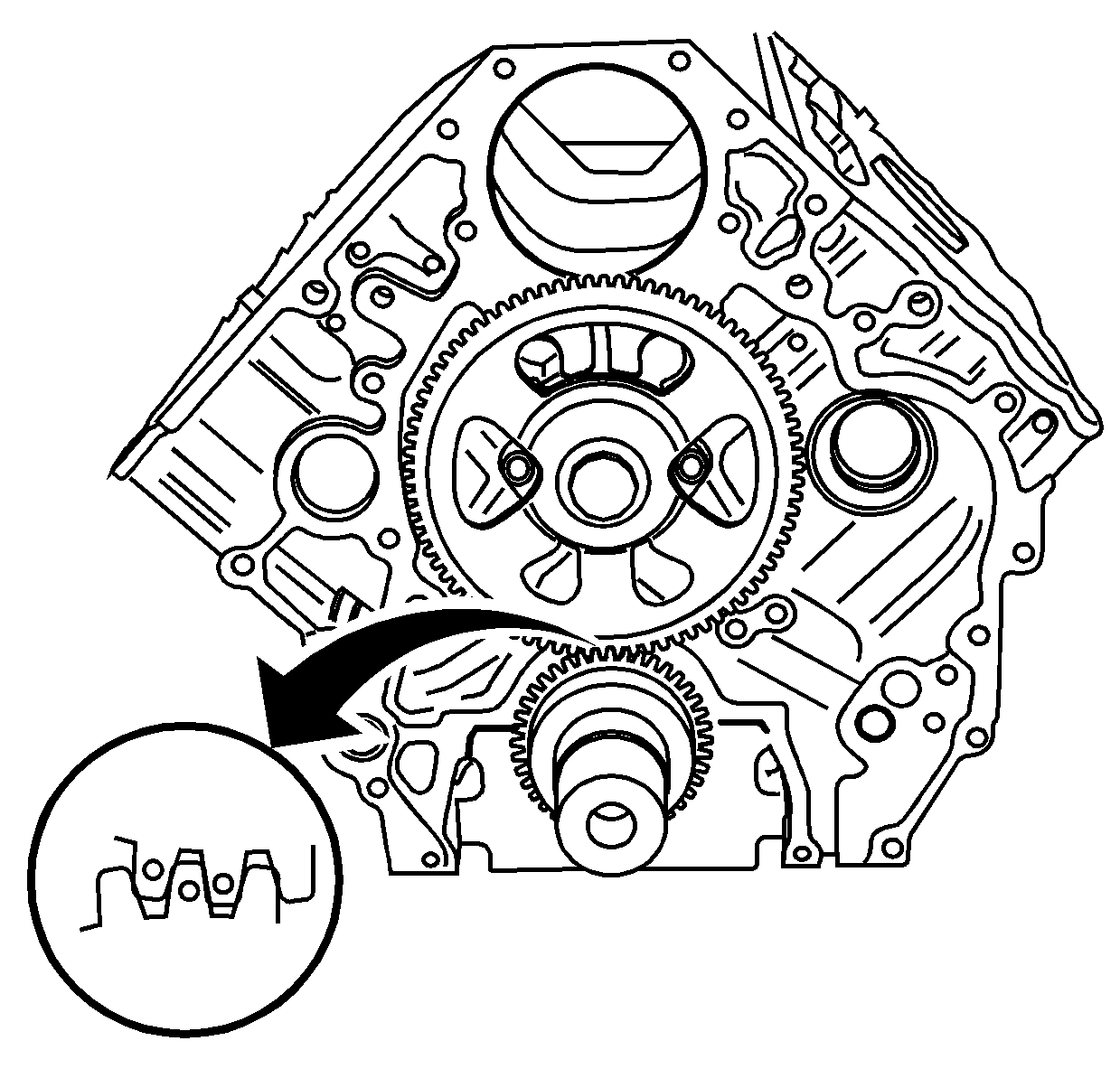
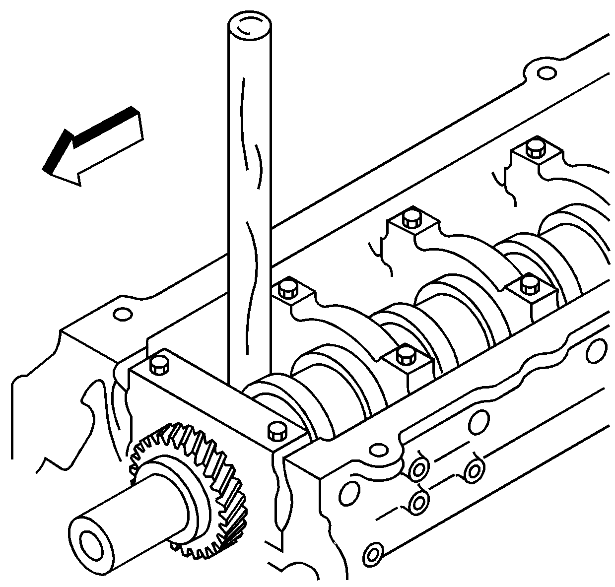
- Install the camshaft and gear assembly into the cylinder block, aligning the camshaft gear to the crankshaft gear as shown.
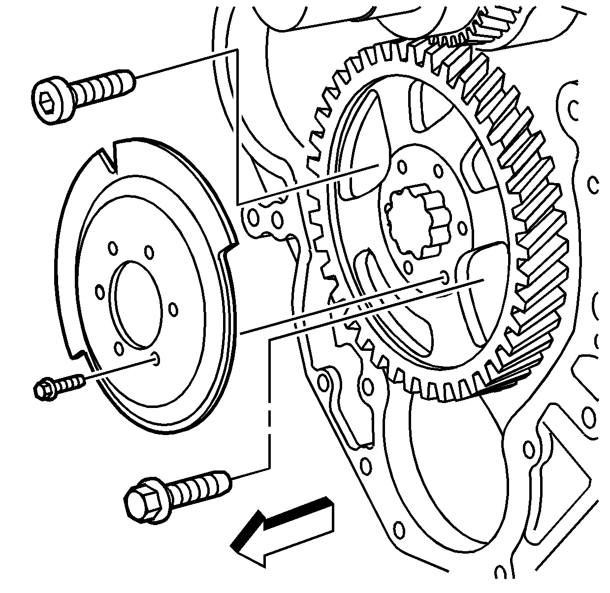
- Install the camshaft thrust plate bolts.
- Install the camshaft position sensor exciter ring to the camshaft gear.
- Install the camshaft position sensor exciter ring bolts.
- Block the crankshaft from turning using a wooden handle.
- Install the new camshaft gear bolt.
- Measure the camshaft end play with J 7872 .
Leave the bolt finger tight.
Notice: Use the correct fastener in the correct location. Replacement fasteners must be the correct part number for that application. Fasteners requiring replacement or fasteners requiring the use of thread locking compound or sealant are identified in the service procedure. Do not use paints, lubricants, or corrosion inhibitors on fasteners or fastener joint surfaces unless specified. These coatings affect fastener torque and joint clamping force and may damage the fastener. Use the correct tightening sequence and specifications when installing fasteners in order to avoid damage to parts and systems.
Tighten
Tighten the camshaft thrust plate bolts to 22 N·m (16 lb ft).
Tighten
Tighten the camshaft position sensor exciter ring bolts to 9 N·m (80 lb in).
Tighten
Tighten the new camshaft gear bolt to 234 N·m (173 lb ft).
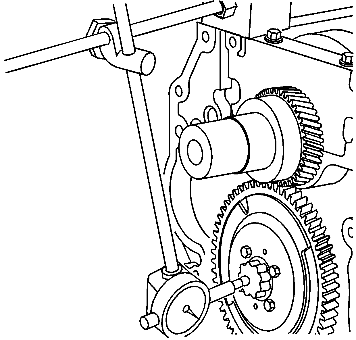
| • | The production value is 0.050-0.114 mm (0.0020-0.0045 in) and service limit is 0.2 mm (0.0079 in). |
| • | Replace the camshaft gear or the camshaft thrust plate if measured value exceeds the service limit. |
