For 1990-2009 cars only
Tools Required
| • | J 2619-01 Slide Hammer |
| • | J 8092 Driver Handle |
| • | J 22912-01 Bearing Remover |
| • | J 29369 Output Shaft Bearing Remover |
| • | J 29369-2 Output Shaft Bearing Remover |
| • | J 9276-21 Slide Hammer |
| • | J 33832 Bearing Installer/Remover |
- Remove the oil pump from the pickup tube and the rear case half.
- Remove the following components from the rear case half:
- Remove the mode fork shift spring from the shift rail.
- Remove the snap ring from the front output shaft.
- Remove the following components from the front case half as an assembly:
- Remove the synchronizer to the mainshaft snap ring.
- Remove the synchronizer assembly from the mainshaft.
- Remove the drive sprocket from the mainshaft.
- Rotate the selector with the shaft in order to obtain clearance when removing the range fork.
- Remove the following components from the front case half:
- Remove the following components from the front case half:
- Remove the input bearing snap ring.
- Use a soft faced hammer to remove the following components from the annulus gear:
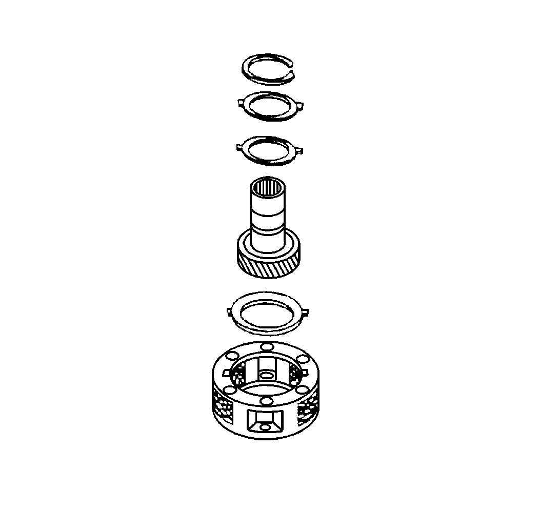
- Remove the input gear to the planetary carrier assembly snap ring.
- Remove the input gear from the planetary carrier.
- Use the J 36370 and the J 8092 to remove the input bearing from the front case half.
- Inspect the needle bearing in the input shaft. Replace the needle if the needle is damaged.
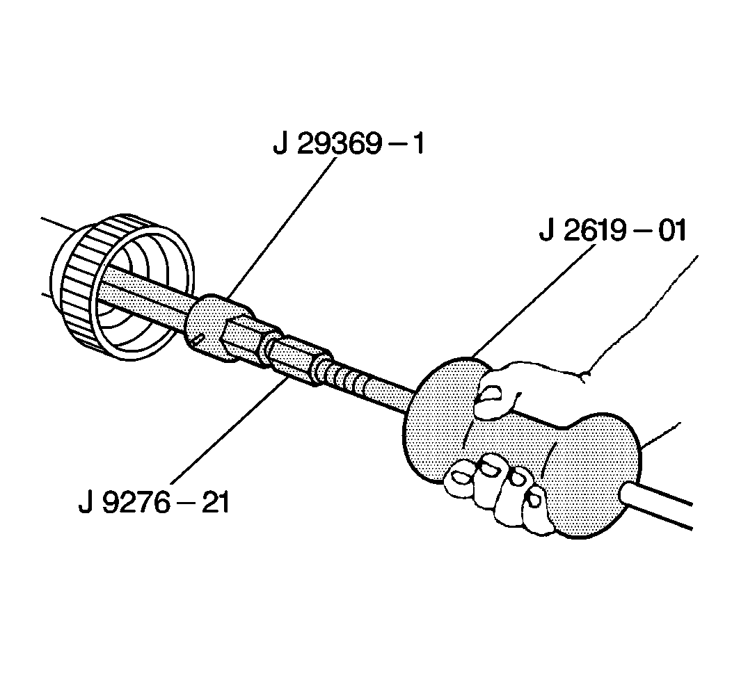
- Use the J 29369 , the J 9276-21 , and the J 2619-01 in order to remove the mainshaft pilot bearing from the input gear.
- Remove the front output bearing snap ring.
- Remove the front output shaft seal from the front case half.
- Use the J 8092 and the J 33832 to remove the front output bearing from the front case half.
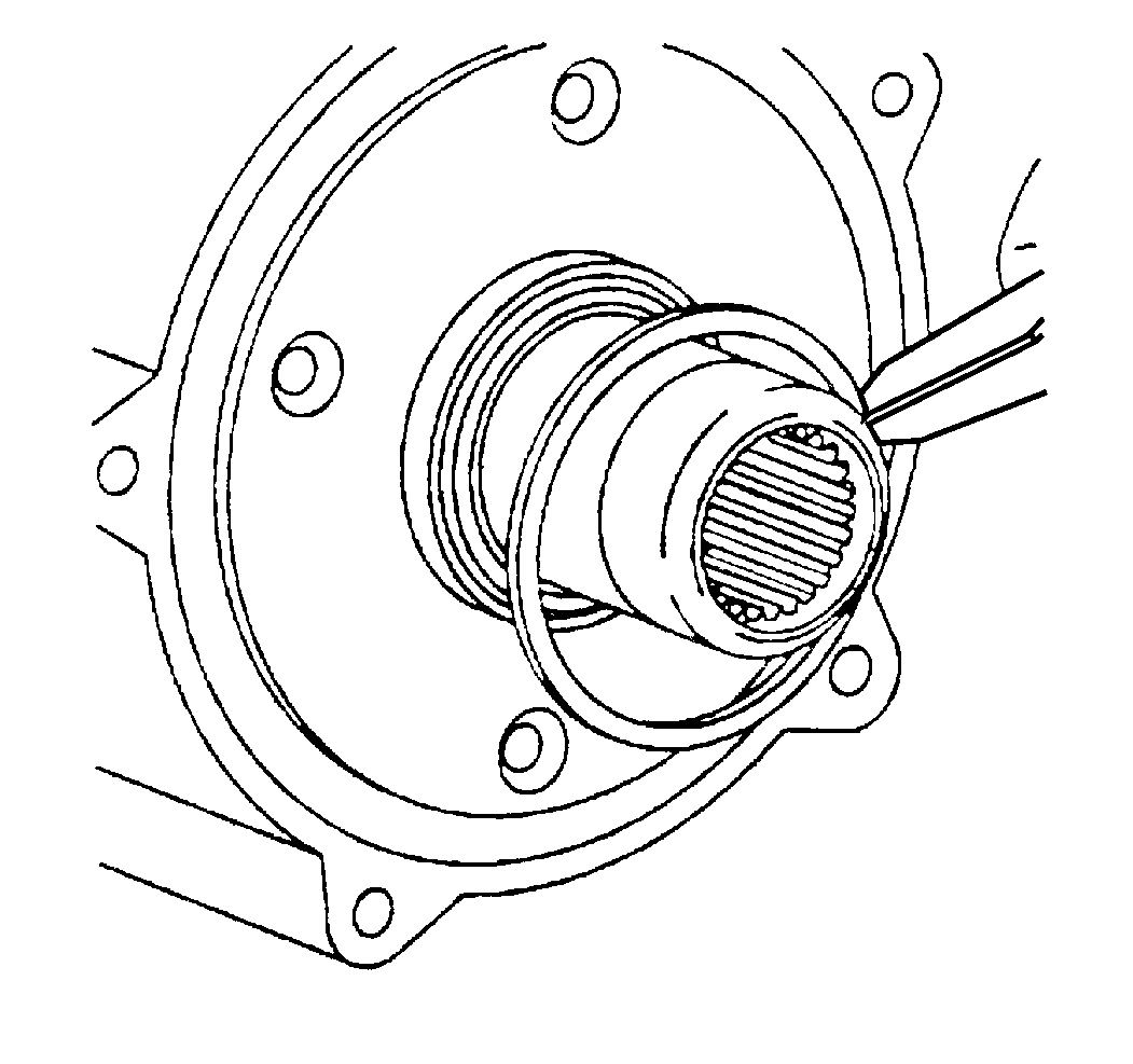
- Remove the seal from the mainshaft extension housing.
- Remove the seal from the input bearing retainer.
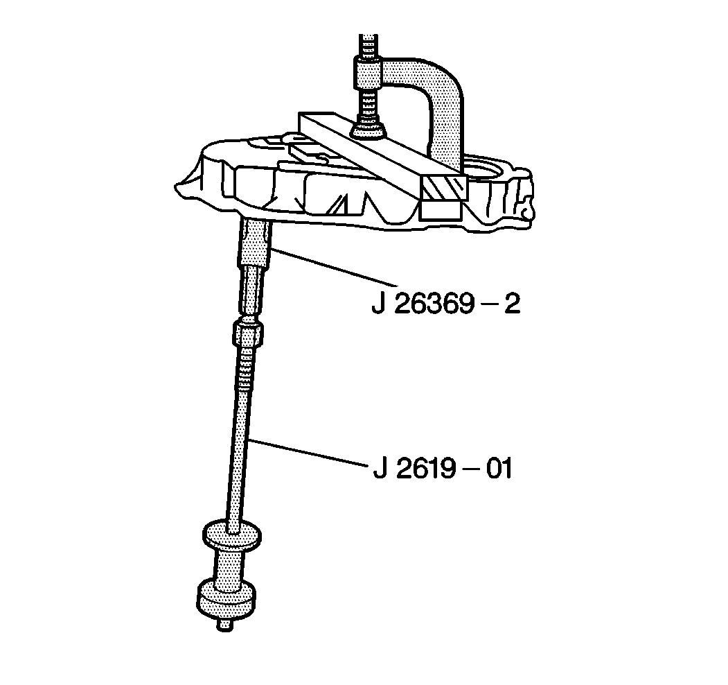
- Insert the J 29369-2 behind the front output needle bearing.
- Use the J 2619-01 in order to drive the bearing from the rear case half.
- Remove the mainshaft bearing from the rear retainer housing.
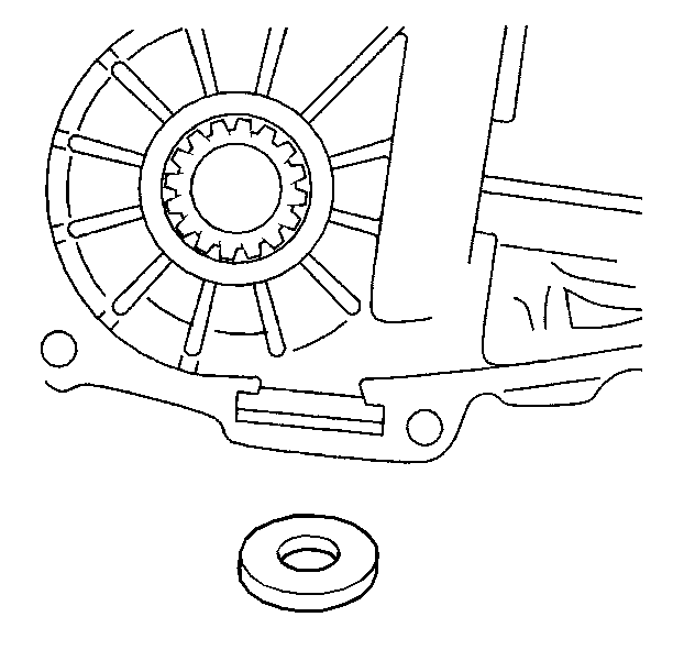
- Remove the magnet from the front case half.
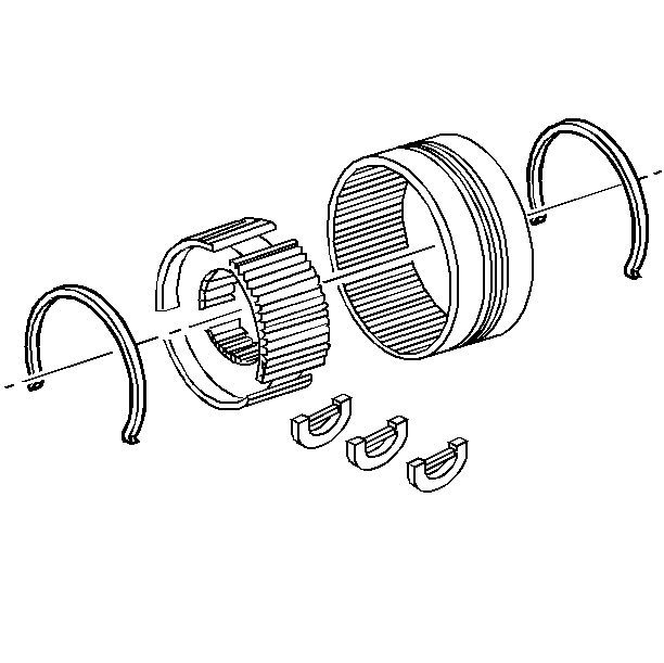
- Scribe the location of the synchronizer sleeve and the hub in order to aid in assembly.
- Remove the main drive synchronizer stop ring from the synchronizer sleeve.
- Remove the 2 spring retainers from the synchronizer hub.
- Remove the synchronizer hub from the synchronizer sleeve.
Important: The annulus case found in this transfer case is not serviceable or removable. The annulus case should only be replaced as a unit with a front case half. If the annulus case is removed, damage to the case will result.
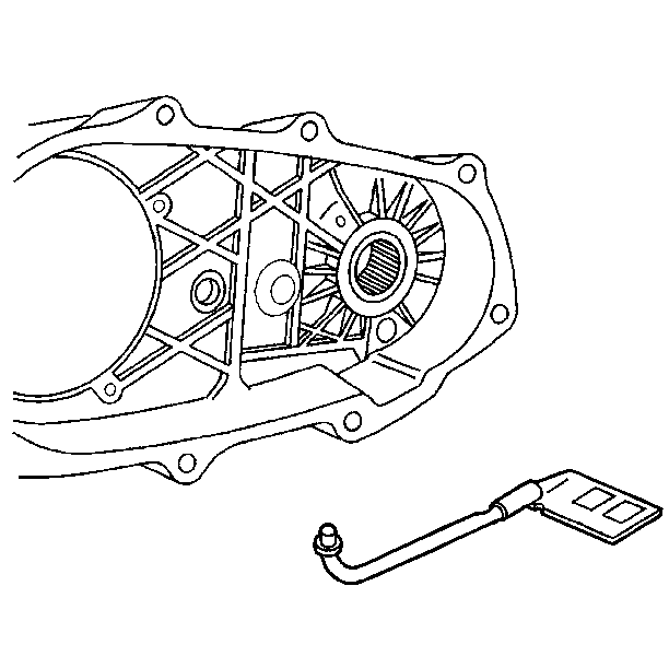
| • | The oil pump pickup tube |
| • | The oil tube connector |
| • | The pump pickup screen |
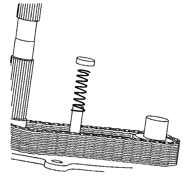
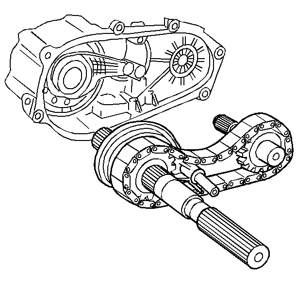
(The mode shift fork and the shift rail will be removed with the mainshaft.)
| • | The mainshaft |
| • | The drive chain |
| • | The driven sprocket |
| • | Note the location of the drive chain master link. |
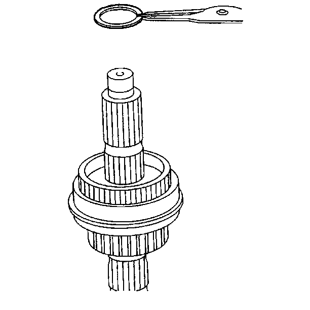
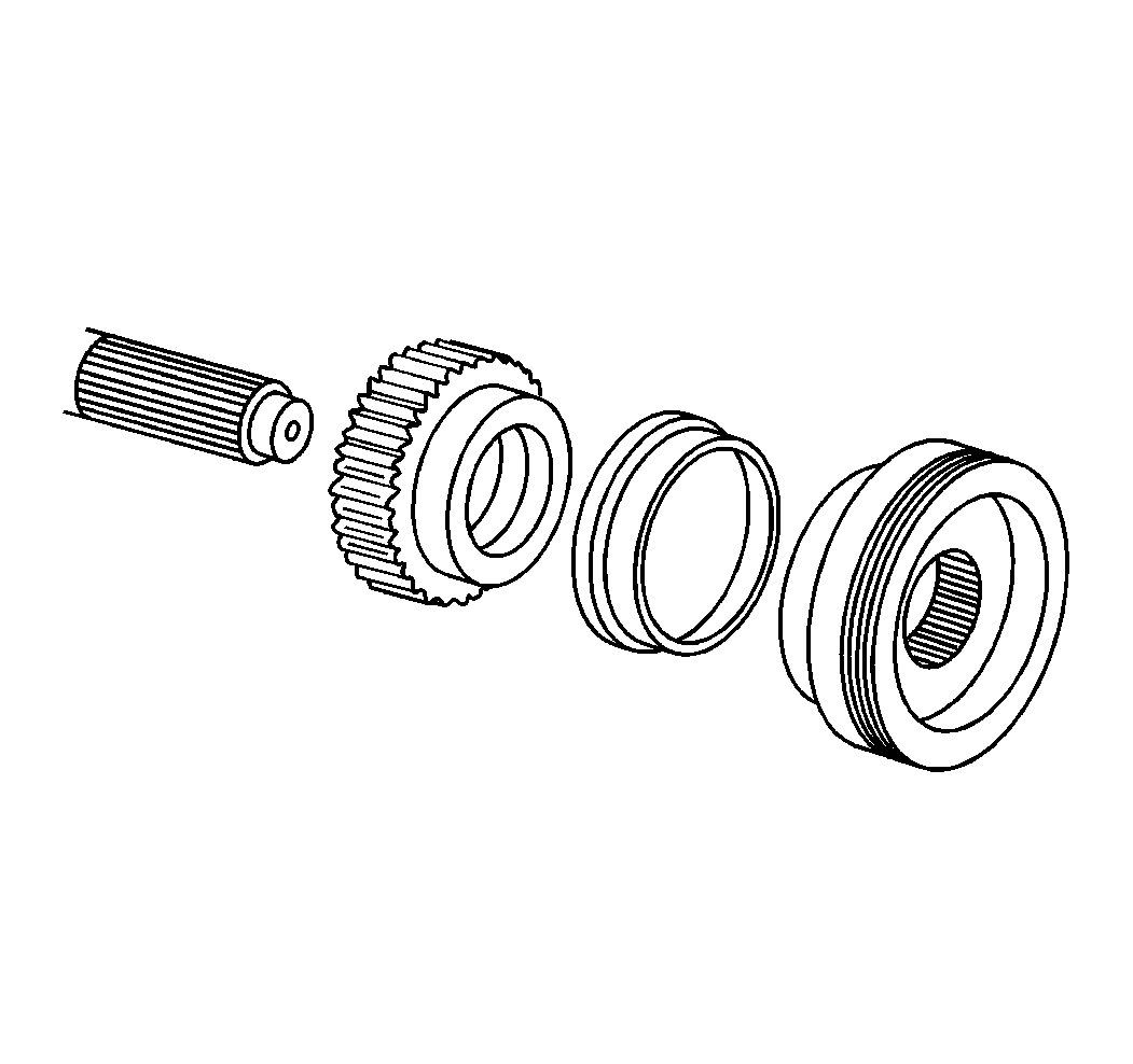
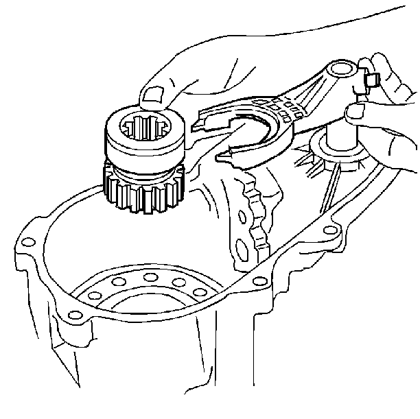
Remove the range shift fork and the range shift hub and the shaft from the planetary carrier.
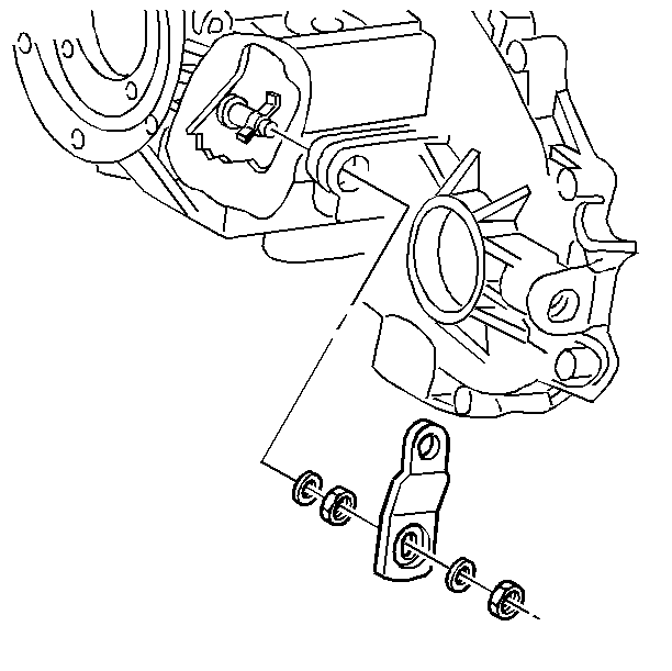
| 10.1. | The shift lever nut |
| 10.2. | The washer |
| 10.3. | The shift lever |
| 10.4. | The selector |
| 10.5. | The shaft assembly |
| 10.6. | The plastic washer |
| 10.7. | The O-ring seal |
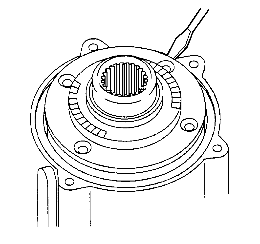
| 11.1. | The input bearing retainer bolts |
| 11.2. | The input bearing retainer |
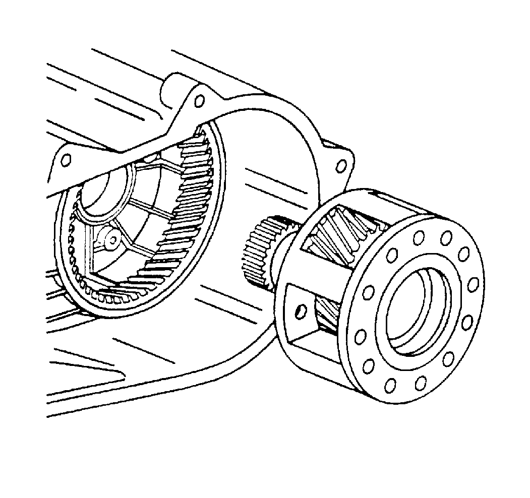
| 13.1. | The planetary carrier |
| 13.2. | The input gear |
Important:
• Do not damage the synchronizer struts when removing the sleeve
from the hub. • The oil pump is not serviceable. The oil pump should be replaced
as a unit only.
