Removal Procedure
- Disconnect the negative battery cable.
- Remove the instrument panel insulator. Refer to the appropriate procedure in Instrument Panel and Console:
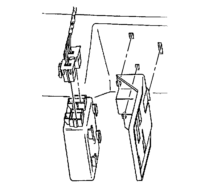
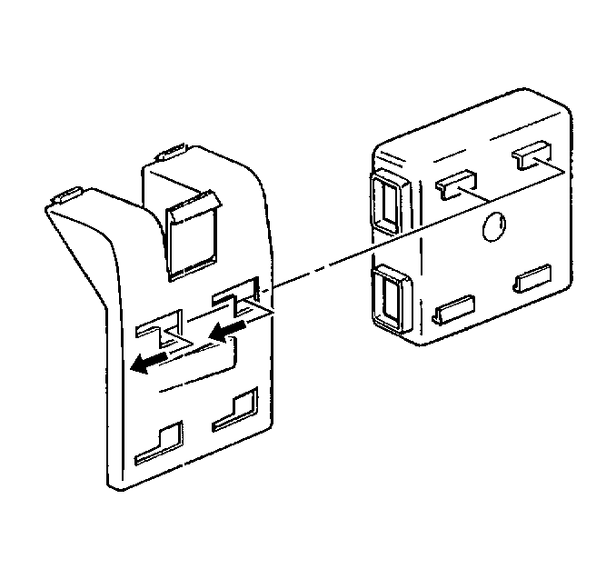
- Slide the daytime running lamp module from the bracket.
- Disconnect the electrical connectors.
Caution: Unless directed otherwise, the ignition and start switch must be in the OFF or LOCK position, and all electrical loads must be OFF before servicing any electrical component. Disconnect the negative battery cable to prevent an electrical spark should a tool or equipment come in contact with an exposed electrical terminal. Failure to follow these precautions may result in personal injury and/or damage to the vehicle or its components.
Installation Procedure
- Position the daytime running lamp module in the bracket.
- Slide the daytime running lamp module into the bracket in order to secure the module.
- Connect the electrical connectors.
- Install the instrument panel insulator. Refer to the appropriate procedure in Instrument Panel and Console:
- Connect the negative battery cable.
Caution: Unless directed otherwise, the ignition and start switch must be in the OFF or LOCK position, and all electrical loads must be OFF before servicing any electrical component. Disconnect the negative battery cable to prevent an electrical spark should a tool or equipment come in contact with an exposed electrical terminal. Failure to follow these precautions may result in personal injury and/or damage to the vehicle or its components.
