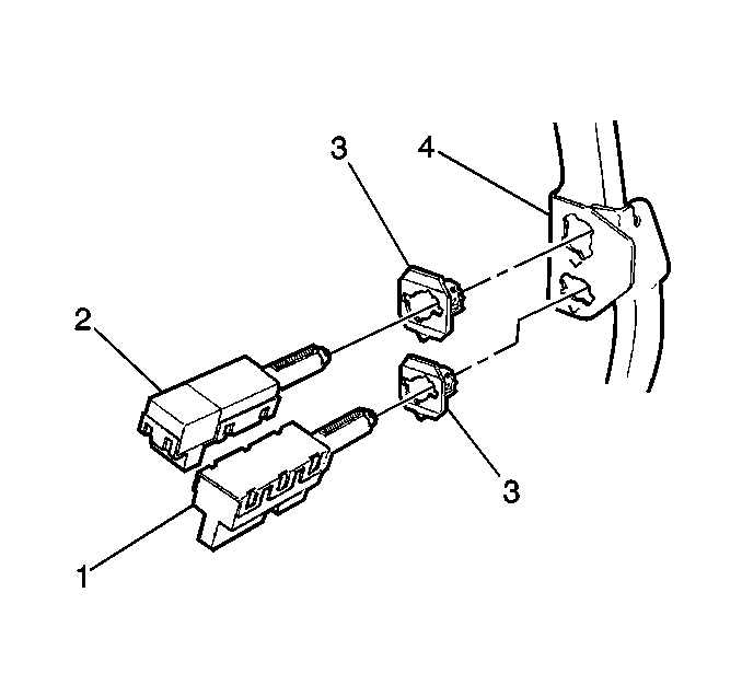
Important: Connect the brake booster pushrod to the brake pedal assembly before
attempting to adjust the release switch assembly (1) and the stoplamp
switch assembly (2).
Notice: Proper stoplamp switch adjustment is essential. Improper stoplamp switch
adjustment could cause brake drag and excessive brake lining wear.
- Press the brake pedal assembly.
- Insert the following components into the retainers until fully
seated against the brake pedal bracket:
| • | The release switch assembly (1) |
| • | The stoplamp switch assembly (2) |
- Twist the switch in order to lock into the desired position.
- In order to ensure a properly adjusted release switch assembly
and a properly adjusted stoplamp switch assembly, use the following brake
pedal assembly travel distances:
| • | The release switch assembly and the stoplamp switch assembly contacts
must be open at a brake pedal travel range of 3.5-12.5 mm (0.125-0.5 in). |
| • | The brake pedal assembly travel is measured at the centerline of the
brake pedal assembly pad. |
| • | The nominal actuation of the stoplamp switch assembly contacts
is about 4.5 mm (0.188 in) after the cruise control switch
assembly contacts close. |

