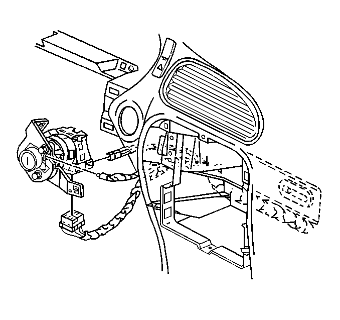
Removal Procedure

- Disconnect negative battery
cable. Refer to
Battery Negative Cable Disconnection and Connection
in Engine Electrical.
- Remove the radio. Refer to
Radio Replacement
in Entertainment.
- Remove the HVAC control head. Refer to
HVAC Control Module Replacement
in HVAC Systems - Manual,
or
HVAC Control Module Replacement
in
HVAC Systems - Automatic.
- Remove the instrument panel (IP) cluster. Refer to
Instrument Cluster Replacement
.
- Remove the ignition switch bezel from the ignition switch, using
a small flat-bladed tool.
- Remove the bolts from ignition switch.
- Reposition the ignition switch for ease of removal.
- Insert the key and turn the ignition switch lock cylinder to the
ACC position.

Important: Ignition switch lock cylinder that won't rotate or is seized.
- Follow the steps below if the ignition switch lock cylinder is seized
or won't rotate.
| 9.1. | Protect the immediate work area with suitable material such as
clean shop towels or a clean fender cover. |
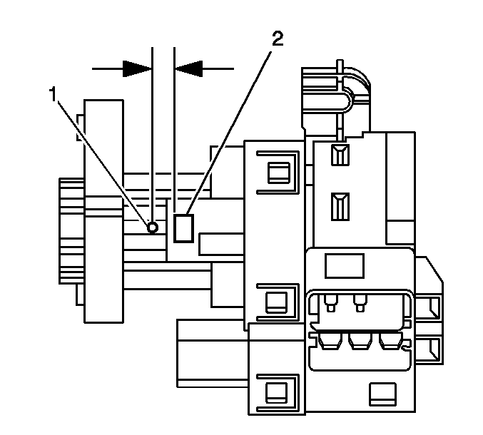
| 9.2. | Locate the surface for the ignition switch lock cylinder release
button (2) on the plastic ignition switch housing and center punch a location
(1) on the "rib" approximately 3/8 inch reward (toward
the key entry end) from the cylinder release button. |
| 9.3. | Carefully drill a pilot hole through the plastic housing with
a 1/8 inch drill bit. |
| 9.4. | Carefully drill a larger hole at the pilot location, and slightly
into the ignition switch lock cylinder surface to break the release button
retaining spring using a 9/32 inch drill bit. |
| 9.5. | Remove portions of the broken spring from the hole using a small
suitable tool. |
| 9.6. | Grasp the ignition switch lock cylinder and remove it from the
switch housing. |
| 9.7. | Remove any plastic "flash" from the drilling operation,
and using compressed air blow out the ignition switch assembly. |
- Depress the transaxle park/lock cable retainer to release, then
pull to remove the park/lock cable from the ignition switch.
- Remove the ignition switch lock cylinder from the ignition switch,
by depressing the retaining tab and pulling the cylinder out with the key.
Important: The pass lock electrical connector can not be removed until the ignition
switch lock cylinder is removed.
- Disconnect the pass lock electrical connector from the ignition switch.
- Disconnect the electrical connectors from the ignition switch.
- Remove the ignition switch through the IP cluster opening.
- Remove the bolts from the ignition switch to the bracket.
- Remove the bracket from the ignition switch.
Installation Procedure

- Install the ignition switch
bracket to the ignition switch.
Notice: Use the correct fastener in the correct location. Replacement fasteners
must be the correct part number for that application. Fasteners requiring
replacement or fasteners requiring the use of thread locking compound or sealant
are identified in the service procedure. Do not use paints, lubricants, or
corrosion inhibitors on fasteners or fastener joint surfaces unless specified.
These coatings affect fastener torque and joint clamping force and may damage
the fastener. Use the correct tightening sequence and specifications when
installing fasteners in order to avoid damage to parts and systems.
- Install the bolts
to the ignition switch bracket.
Tighten
Tighten the ignition switch bracket bolts to 6 N·m (53 lb in).
- Install the ignition switch into position through the IP cluster
opening.
- Connect the electrical connectors to the ignition switch.
- Connect the pass lock electrical connector from the ignition switch.
- Connect the park/lock cable to the ignition switch.
- Install the bolts to the ignition switch.
Tighten
Tighten the ignition switch bolts to 6 N·m (53 lb in).
- Insert the key and turn the ignition switch lock cylinder to the
ACC position.
- Align and press ignition switch lock cylinder into place.
Important: Ignition switch lock cylinder that previously would not rotate or was
seized.
- Follow steps 10.1 through 10.3 below if ignition switch lock cylinder
previously removed was seized or would not rotate.
| 10.1. | Install the new ignition switch lock cylinder as required by rotating
both the cylinder and the ignition switch to the "ON" position. |
| 10.2. | Push the ignition switch lock cylinder into the ignition switch
housing until fully seated. |
| 10.3. | It may be necessary to slightly depress the release button as
it passes by the 9/32" hole previously drilled in the ignition
switch housing. |
- Remove the key from the ignition switch.
- Install the IP cluster. Refer to
Instrument Cluster Replacement
.
- Install the HVAC control head. Refer to
HVAC Control Module Replacement
in HVAC Systems - Manual,
or
HVAC Control Module Replacement
in
HVAC Systems - Automatic.
- Install the radio. Refer to
Radio Replacement
in Entertainment.
- Connect negative battery cable. Refer to
Battery Negative Cable Disconnection and Connection
in Engine
Electrical.


