For 1990-2009 cars only
Removal Procedure
- Raise the vehicle. Refer to Lifting and Jacking the Vehicle in General Information.
- Remove the fasteners from the front portion of the splash shield in the left front wheel well . Refer to Front Fender Liner Replacement in Body Front End.
- Reposition the splash shield in order to gain access to the pump and bracket assembly.
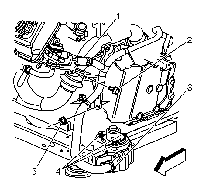
- Compress the pinch clamp and remove the outlet hose from the pump (3).
- Remove the inlet hose from the pump.
- Remove the pump fasteners.
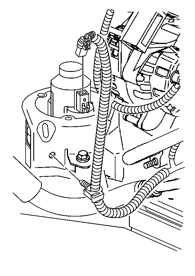
- Reposition pump to gain access to the electrical connector.
- Disconnect the pump electrical connector.
- Remove the pump from the vehicle.
- Transfer parts as necessary.
Installation Procedure
- Connect the pump electrical connector.
- Attach the pump to the bracket using the fasteners.
- Install the inlet hose to the pump.
- Compress the pinch clamp and install the outlet hose to the pump (3).
- Raise the wheel well splash shield into position. Refer to Front Fender Liner Replacement in Body Front End.
- Install the fasteners to the wheel well splash shield.
- Lower the vehicle.
Notice: Use the correct fastener in the correct location. Replacement fasteners must be the correct part number for that application. Fasteners requiring replacement or fasteners requiring the use of thread locking compound or sealant are identified in the service procedure. Do not use paints, lubricants, or corrosion inhibitors on fasteners or fastener joint surfaces unless specified. These coatings affect fastener torque and joint clamping force and may damage the fastener. Use the correct tightening sequence and specifications when installing fasteners in order to avoid damage to parts and systems.
Tighten
Tighten the fasteners to 9 N·m (80 lb in).
