EGR Inlet Pipe
Removal Procedure
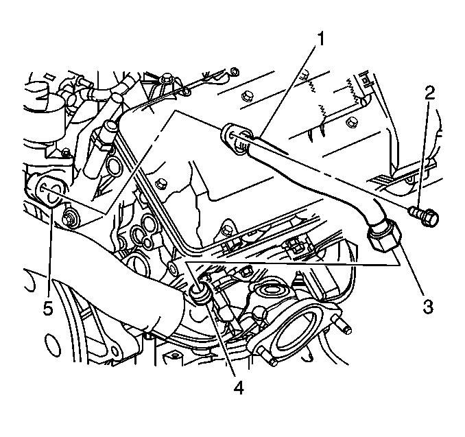
- Remove the mounting bolt (2) that attaches the exhaust gas recirculation (EGR) inlet pipe flange to the coolant crossover assembly (5).
- Remove the nut that attaches the EGR inlet pipe flare to the rear exhaust manifold.
Installation Procedure
- Hand tighten the flange mounting bolt (2) to the coolant crossover assembly (4).
- Attach the EGR inlet pipe nut (3) to the rear exhaust manifold (4).
Notice: Use the correct fastener in the correct location. Replacement fasteners must be the correct part number for that application. Fasteners requiring replacement or fasteners requiring the use of thread locking compound or sealant are identified in the service procedure. Do not use paints, lubricants, or corrosion inhibitors on fasteners or fastener joint surfaces unless specified. These coatings affect fastener torque and joint clamping force and may damage the fastener. Use the correct tightening sequence and specifications when installing fasteners in order to avoid damage to parts and systems.
Tighten
| • | Tighten the nut to 60 N·m (44 lb ft). |
| • | Tighten the mounting bolt to 24 N·m (18 lb ft). |
EGR Outlet Pipe
Removal Procedure
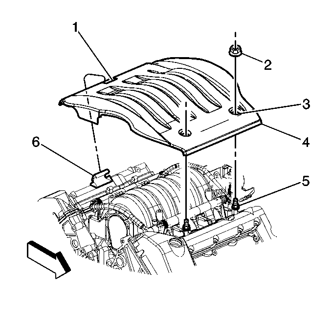
- Remove the mounting nuts (2) from the fuel injector sight shield .
- Lift the injector sight shield off the mounting studs by lifting at the front (4) of the cover.
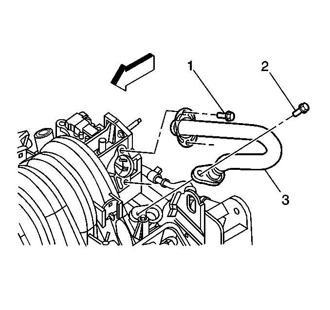
- Remove the mounting bolts (1) retaining the outlet pipe upper flange to the intake manifold.
- Remove the lower flange mounting bolt (2) from the coolant crossover assembly.
- Remove the EGR outlet pipe.
Installation Procedure
- Install the EGR outlet pipe (3) between the intake manifold and the coolant crossover assembly.
- Install the lower flange mounting bolt (2) into the coolant crossover assembly.
- Install the upper flange mounting bolts (1) into the intake manifold.
- Keeping the injector sight shield as level as possible, place the rear (1) of the shield under the mounting bracket (6).
- Align and press the injector sight shield (4) onto the mounting studs (5).
- Install the mounting nuts (2) onto the mounting studs (5).
Notice: Use the correct fastener in the correct location. Replacement fasteners must be the correct part number for that application. Fasteners requiring replacement or fasteners requiring the use of thread locking compound or sealant are identified in the service procedure. Do not use paints, lubricants, or corrosion inhibitors on fasteners or fastener joint surfaces unless specified. These coatings affect fastener torque and joint clamping force and may damage the fastener. Use the correct tightening sequence and specifications when installing fasteners in order to avoid damage to parts and systems.
Tighten
Tighten the bolt to 24 N·m (18 lb ft).
Tighten
Tighten the bolts to 10 N·m (89 lb in)
Tighten
Tighten the nuts to 3 N·m (27 lb in).
