For 1990-2009 cars only
Tools Required
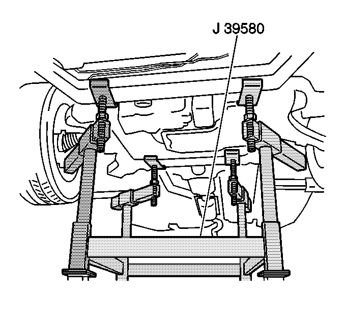
J 39580 Universal Engine Support Table
Removal Procedure
- Install the engine support fixture. Refer to Engine Support Fixture in Engine Mechanical.
- Raise and support the vehicle. Refer to Lifting and Jacking the Vehicle in General Information.
- Remove the front tires and wheels. Refer to Tire and Wheel Removal and Installation in Tires and Wheels.
- Disconnect the fog lamp electrical connectors and position aside.
- Remove the radiator lower air deflector. Refer to Radiator Air Baffle Assemblies and Deflectors in Engine Cooling.
- Remove the positive battery cable and retainers from the frame and position aside. Refer to Battery Positive Cable Replacement in Engine Electrical.
- Disconnect the power steering cooler pipe from the frame. Refer to Power Steering Cooler Pipe/Hose Replacement in Power Steering.
- Secure the power steering cooler.
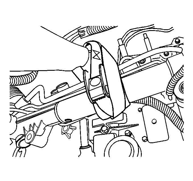
- Remove the stabilizer shaft links and rotate the stabilizer shaft up to gain access to the power steering gear mounting bolts. Refer to Stabilizer Shaft Link Replacement in Front Suspension.
- Remove the power steering gear mounting bolts. Refer to Steering Gear Replacement in Power Steering.
- Secure the power steering gear.
- Remove the engine mount-to-frame nuts. Refer to Engine Front Mount Replacement in Engine Mechanical - 3.5L.
- Remove the transaxle mount-to-frame nuts. Refer to Transmission Mount Replacement in Automatic Transaxle - 4T65-E.
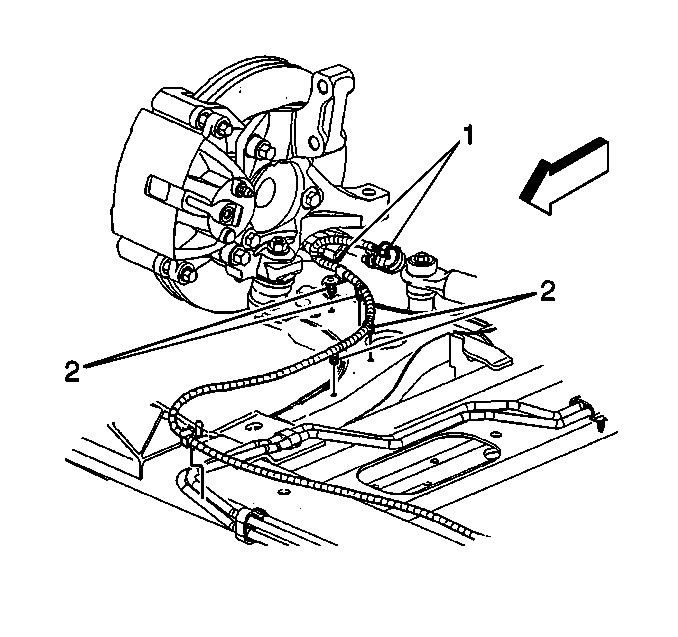
- Disconnect both front wheel speed sensor connectors (1).
- Remove both front wheel speed harness retainers (2) from the frame and the lower control arms.
- Separate both of the lower ball joints from the steering knuckle. Refer to Lower Control Arm Replacement in Front Suspension.
- Lower the vehicle until the frame contacts the J 39580 .
- Remove and DISCARD the front frame-to-body bolts.
- Remove and DISCARD the rear frame-to-body bolts.
- Raise the vehicle in order to separate the frame from the body.
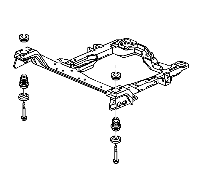
- If you are replacing the frame, remove the following components:
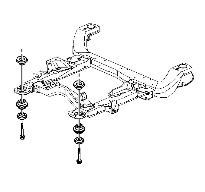
| • | Both of the lower control arms. Refer to Lower Control Arm Replacement in Front Suspension. |
| • | The stabilizer shaft. Refer to Stabilizer Shaft Replacement in Front Suspension. |
| • | The spacers, the upper insulator, the lower insulator, and the retainers. Refer to Front Frame Cushion or Insulator Replacement and to Rear Frame Cushion or Insulator Replacement . |
Installation Procedure
- If you are replacing the frame, install the following components:
- Position the engine support table with the frame under the vehicle.
- Lower the vehicle to the frame.
- Loosely install the NEW rear frame-to-body bolts.
- Loosely install the NEW front frame-to-body bolts.
- Align the frame to the body by inserting two 19 X 203 mm (0.74 X 8.0 in) pins in the alignment holes on the right side of the frame.
- Connect both the lower ball joints to the steering knuckle. Refer to Lower Control Arm Replacement in Front Suspension.
- Install the engine mount-to-frame nuts. Refer to Engine Front Mount Replacement in Engine Mechanical - 3.5L.
- Install the transaxle mount-to-frame nuts. Refer to Transmission Mount Replacement in Automatic Transaxle - 4T65-E.
- Install the steering gear mounting bolts. Refer to Steering Gear Replacement in Power Steering.
- Install the stabilizer shaft links. Refer to Stabilizer Shaft Link Replacement in Front Suspension.
- Connect both front wheel speed sensor connectors (1).
- Install both front wheel speed harness retainers (2) to the frame and the lower control arm.
- Install the positive battery cable and retainers to the frame. Refer to Battery Positive Cable Replacement in Engine Electrical.
- Install the power steering cooler pipe. Refer to Power Steering Cooler Pipe/Hose Replacement in Power Steering.
- Install the radiator lower air deflector. Refer to Radiator Air Baffle Assemblies and Deflectors in Engine Cooling.
- Install the fog lamp electrical connectors to the fog lamps.
- Install the front tires and wheels. Refer to Tire and Wheel Removal and Installation in Tires and Wheels.
- Lower the vehicle.
- Remove the engine support fixture. Refer to Engine Support Fixture in Engine Mechanical - 3.5L.
- Inspect the front wheel alignment. Refer to Wheel Alignment Measurement in Wheel Alignment.
- Perform the steering angle sensor centering procedure. Refer to Steering Angle Sensor Centering in Antilock Brake System.
| • | Both of the lower control arms. Refer to Lower Control Arm Replacement in Front Suspension. |
| • | The stabilizer shaft. Refer to Stabilizer Shaft Replacement in Front Suspension. |
| • | The spacers, the upper insulator, the lower insulator, and the retainers. Refer to Front Frame Cushion or Insulator Replacement and to Rear Frame Cushion or Insulator Replacement . |


Notice: Use the correct fastener in the correct location. Replacement fasteners must be the correct part number for that application. Fasteners requiring replacement or fasteners requiring the use of thread locking compound or sealant are identified in the service procedure. Do not use paints, lubricants, or corrosion inhibitors on fasteners or fastener joint surfaces unless specified. These coatings affect fastener torque and joint clamping force and may damage the fastener. Use the correct tightening sequence and specifications when installing fasteners in order to avoid damage to parts and systems.
Tighten
Tighten the frame bolts to 180 N·m (133 lb ft).

