Refer to Engine Controls Schematics
Crankshaft and Camshaft Position Sensor
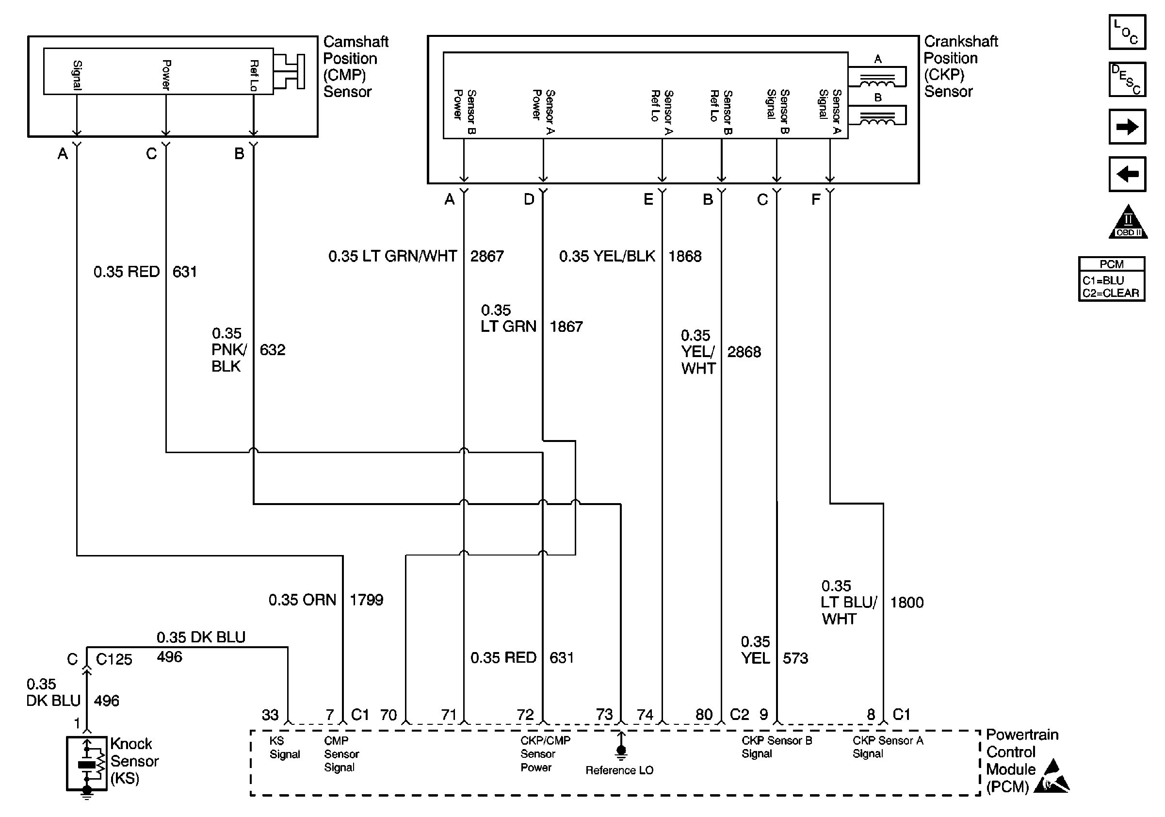
.
Circuit Description
This diagnostic trouble code (DTC) indicates that there is an intermittent problem with the relationship between crankshaft position (CKP) sensor A and CKP sensor B.
Conditions for Running the DTC
The engine is cranking or running
Conditions for Setting the DTC
The PCM detects an intermittent loss of match between the two CKP sensor signals.
Action Taken When the DTC Sets
| • | The PCM illuminates the malfunction indicator lamp (MIL) on the second consecutive ignition cycle that the diagnostic runs and fails. |
| • | The PCM records the operating conditions at the time the diagnostic fails. The first time the diagnostic fails, the PCM stores this information in the Failure Records. If the diagnostic reports a failure on the second consecutive ignition cycle, the PCM records the operating conditions at the time of the failure. The PCM writes the conditions to the Freeze Frame and updates the Failure Records. |
Conditions for Clearing the MIL/DTC
| • | The PCM turns the MIL OFF after 3 consecutive drive trips during which the diagnostic runs and passes. |
| • | A last test failed, or the current DTC, clears when the diagnostic runs and passes. |
| • | A History DTC clears after 40 consecutive warm-up cycles, if no other emission related diagnostic failures are reported. |
| • | Use a scan tool in order to clear the MIL diagnostic trouble code. |
| • | Interrupting the PCM battery voltage may or may not clear DTCs. This practice is not recommended. Refer to Powertrain Control Module Description , Clearing Diagnostic Trouble Codes. |
Diagnostic Aids
Notice: Use the connector test adapter kit J 35616-A for any test that
requires probing the following items:
• The PCM harness connectors • The electrical center fuse/relay cavities • The component terminals • The component harness connector
If the problem is intermittent, refer to Intermittent Conditions .
Test Description
The numbers below refer to the step numbers on the diagnostic table.
Step | Action | Value(s) | Yes | No |
|---|---|---|---|---|
1 | Did you perform the Powertrain On-Board Diagnostic (OBD) System Check? | -- | ||
2 | Is DTC P0335 or P0385 also set? | -- | Go to the applicable DTC table | |
Does CKP Sensor Status indicate Time A? | -- | |||
4 | Does CKP Sensor Status indicate Time B? | -- | ||
5 | Move the related harnesses and connectors, by hand only, while monitoring the scan tool display. Does CKP Sensor Status change to Time A? | -- | ||
6 | Did CKP Sensor Status change to Time B? | -- | Go to Intermittent Conditions |
