Removal Procedure
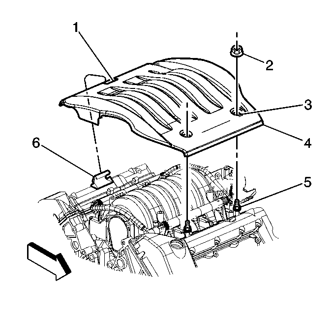
- Remove the mounting nuts retaining the injector sight shield.
- Lift the injector sight shield off the mounting studs by lifting at the front (4) of the cover.
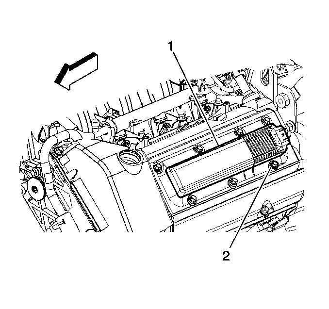
- Disconnect the electrical connector from the ignition control module.
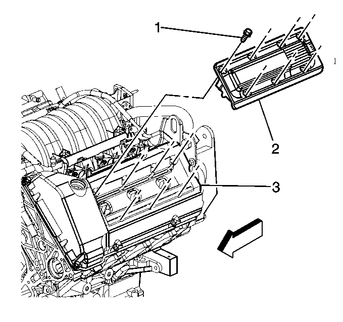
- Remove the 7 bolts (2) retaining the ignition cassette to the cam cover.
- Gently pry the cassette (2) away from the cam cover (3) using a screwdriver. Protect finished surfaces from scratches with a shop cloth. Pry a small amount in several locations around the edge of the cassette in order to lift the assembly as evenly as possible. Do not insert the screwdriver far enough to tear the perimeter seal on the cassette.
- On some vehicles the oil level indicator tube may interfere with the removal of the front bank coil cassette. Remove the bolt retaining the oil level indicator tube and move the oil level indicator tube if necessary.
- Lift the cassette straight up off the spark plugs.
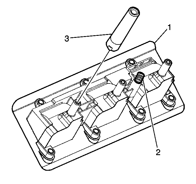
- Remove the secondary boots (3) from the spark plugs or the ignition coils using a twisting motion to break the seal. Use J 43094 spark plug boot removal tool. Do not use pliers, screwdrivers, or any unauthorized tool to remove the boots.
Installation Procedure
Important: When servicing the ignition system components, use the following recommended
procedures:
• Do not re-install any component that has visible signs of damage. • Check the boots for a missing or damaged internal spring. • Ensure that the boots are installed right-side up. • Ensure that the ignition cassette-to-cam cover ground spring (2)
is in place. • Repair a torn perimeter seal with an RTV sealant. • Clean all the mounting surfaces before re-installing any components.
- Install the boots (3) onto the ignition coils until bottomed out.
- Install the cassette assembly (2) straight down onto the spark plugs.
- Install the 7 bolts (2) that retain the ignition cassette to the cam cover .
- Connect the electrical connector to the ignition control module.
- If the oil level indicator tube was moved during disassembly, move the tube back into position and install the retaining bolt.
- Keeping the injector sight shield as level as possible, place the rear (1) of the shield under the mounting bracket (6).
- Align and press the injector sight shield (4) onto the mounting studs (5).
- Install the mounting nuts (2) onto the mounting studs (5).
If this is not possible due to space limitations (rear bank), just-start the boots onto the spark plugs and then align and start the ignition coil towers into the boots. Press the coil assembly (2) down onto the plugs as straight as possible.
Notice: Use the correct fastener in the correct location. Replacement fasteners must be the correct part number for that application. Fasteners requiring replacement or fasteners requiring the use of thread locking compound or sealant are identified in the service procedure. Do not use paints, lubricants, or corrosion inhibitors on fasteners or fastener joint surfaces unless specified. These coatings affect fastener torque and joint clamping force and may damage the fastener. Use the correct tightening sequence and specifications when installing fasteners in order to avoid damage to parts and systems.
Tighten
Tighten the bolts to 9.5 N·m (84 lb in).
Tighten
Tighten the retaining bolt to 9 N·m (80 lb in).
Tighten
Tighten the mounting nuts to 3 N·m (27 lb in).
