Refer to Engine Controls Schematics
Heated O2 Sensors
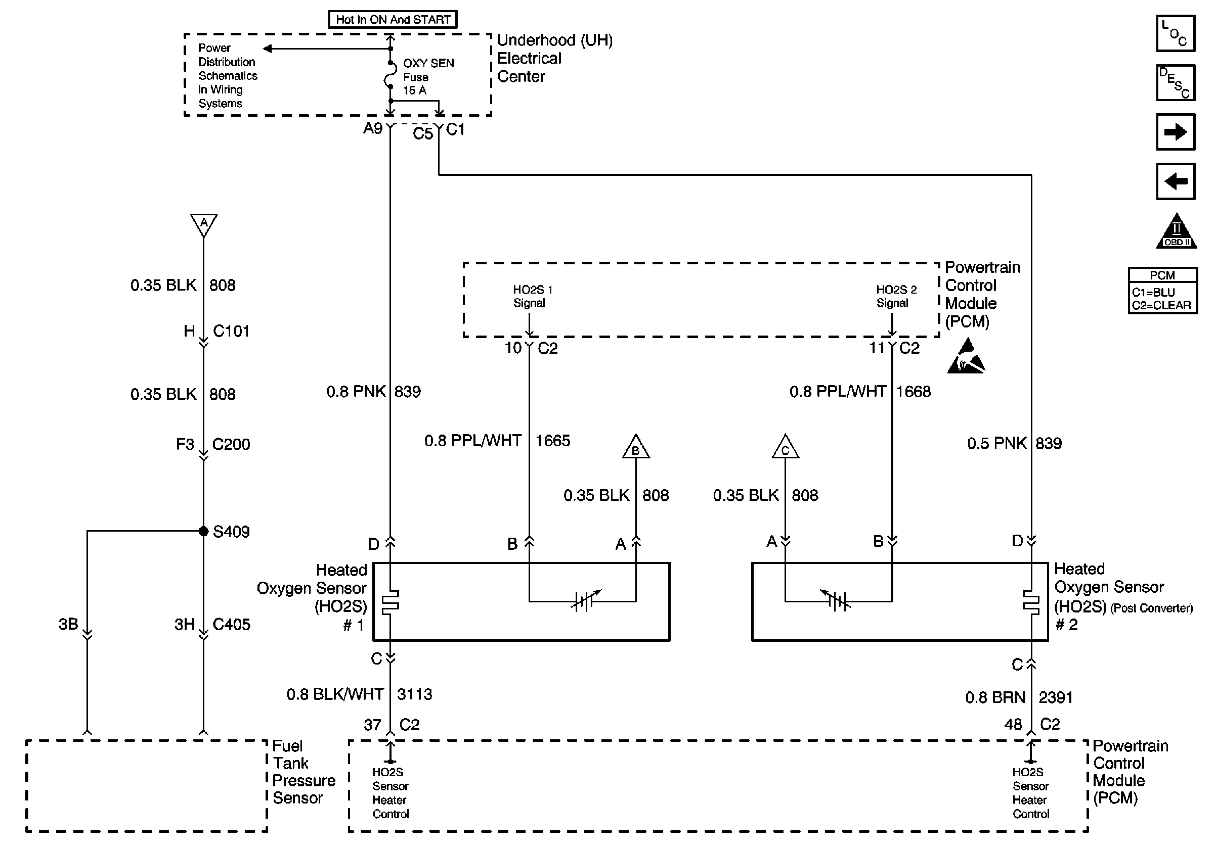
.
Circuit Description
The powertrain control module (PCM) monitors the heated oxygen sensor (HO2S) activity for 100 seconds. During this test period, the PCM counts the number of times that the HO2S signal voltage crosses the rich to lean and lean to rich thresholds. If the PCM determines that the HO2S did not switch enough times, DTC P1133 will be set. A lean to rich switch is determined when the HO2S voltage changes from less than 300 mV to more than 600 mV. A rich to lean switch is determined when the HO2S voltage changes from more than 600 mV to less than 300 mV.
Conditions for Running the DTC
| • | The following types of diagnostic trouble codes (DTCs) are not active: |
| • | Fuel trim |
| • | Fuel injector circuit |
| • | Misfire |
| • | Evaporative emission (EVAP) system |
| • | Exhaust gas recirculation (EGR) system |
| • | AIR system |
| • | Throttle position (TP) sensor |
| • | Intake air temperature (IAT) sensor |
| • | Manifold absolute pressure (MAP) sensor |
| • | Engine coolant temperature (ECT) sensor |
| • | Crankshaft position (CKP) sensor |
| • | Mass air flow (MAF) sensor |
| • | P0131, P0132 or P0135 not set |
| • | The system voltage is more than 9 volts. |
| • | The engine is running in closed loop |
| • | The engine is running for at least 3.3 minutes. |
| • | The ECT is more than 75°C (167°F) |
| • | The engine speed is between 1,000-3,000 RPM |
| • | The MAF is between 15-40 gm/s |
| • | The above conditions are stable for 3 seconds |
Conditions for Setting the DTC
| • | The above conditions are present for a 90 second monitoring period. |
| • | The PCM monitors fewer than 5 rich to lean and 5 lean to rich switches for HO2S 1. |
Action Taken When the DTC Sets
| • | The PCM illuminates the malfunction indicator lamp (MIL) on the second consecutive ignition cycle that the diagnostic runs and fails. |
| • | The PCM records the operating conditions at the time the diagnostic fails. The first time the diagnostic fails, the PCM stores this information in the Failure Records. If the diagnostic reports a failure on the second consecutive ignition cycle, the PCM records the operating conditions at the time of the failure. The PCM writes the conditions to the Freeze Frame and updates the Failure Records. |
Conditions for Clearing the MIL/DTC
| • | The PCM turns the MIL OFF after 3 consecutive drive trips during which the diagnostic runs and passes. |
| • | A last test failed, or the current DTC, clears when the diagnostic runs and passes. |
| • | A History DTC clears after 40 consecutive warm-up cycles, if no other emission related diagnostic failures are reported. |
| • | Use a scan tool in order to clear the MIL diagnostic trouble code. |
| • | Interrupting the PCM battery voltage may or may not clear DTCs. This practice is not recommended. Refer to Powertrain Control Module Description , Clearing Diagnostic Trouble Codes. |
Diagnostic Aids
Notice: Use the connector test adapter kit J 35616-A for any test that
requires probing the following items:
• The PCM harness connectors • The electrical center fuse/relay cavities • The component terminals • The component harness connector
A malfunction in the HO2S heater ignition feed or ground circuit may cause the DTC to set. Check HO2S heater circuitry for intermittent malfunctions or poor connections. If connections and wiring are OK and the DTC continues to set, the HO2S may be at fault.
Reviewing the Failure Records vehicle mileage since the diagnostic test last failed may help determine how often the condition that caused the DTC to set occurs. This may assist in diagnosing the condition.
If the problem is intermittent, refer to Intermittent Conditions .
Test Description
The numbers below refer to the step numbers on the diagnostic table.
-
This step checks for correct sensor activity. When in Closed Loop fuel control, the HO2S voltage should rapidly swing above and below the bias voltage.
-
This step checks the PCM and the high and low circuits between the PCM and the HO2S connector for correct operation.
-
This step checks for correct HO2S heater circuit operation up to the HO2S connector.
-
This step checks for correct circuit resistance between the HO2S low circuit and the PCM ground.
-
This step checks for proper circuit resistance between the HO2S low circuit and the PCM ground with a COLD sensor. A loose HO2S or faulty thread to exhaust electrical contact will cause higher resistance when the HO2S is cold. Although 500 ohms is allowed, typical resistance should be less than 50 ohms.
Step | Action | Values | Yes | No | ||||||||||||||||||
|---|---|---|---|---|---|---|---|---|---|---|---|---|---|---|---|---|---|---|---|---|---|---|
1 | Did you perform the Powertrain On-Board Diagnostic (OBD) System Check? | -- | ||||||||||||||||||||
Is the HO2S voltage fixed within the voltage range specified? | 351-551 mV | |||||||||||||||||||||
3 |
Was a condition found and repaired? | -- | Go to Dignostic Aids | |||||||||||||||||||
Is the HO2S voltage less than the value specified? | 20 mV | |||||||||||||||||||||
5 |
Is the individual resistance of both circuits less than the specified value? | 5 ohms | ||||||||||||||||||||
6 |
Was a PCM terminal repair made? | -- | ||||||||||||||||||||
Is the test lamp illuminated? | -- | |||||||||||||||||||||
Is the resistance measured less than the value specified? | 500 ohms | |||||||||||||||||||||
9 | Repair the circuit that measured high resistance. Refer to Wiring Repairs in Wiring Systems. Is the action complete? | -- | -- | |||||||||||||||||||
10 | Repair the HO2S heater ignition or ground circuit. Refer to Wiring Repairs in Wiring Systems. Probable causes of the problem include the following:
Is the action complete? | -- | -- | |||||||||||||||||||
11 | Repair the high resistance between the HO2S low circuit and the PCM ground circuit. Refer to Wiring Repairs in Wiring Systems. Probable causes of the problem include the following:
Is the action complete? | -- | -- | |||||||||||||||||||
12 |
The leak may be very small and will typically will be within 12 inches of the suspect HO2S. Was an exhaust system repair made? | -- | ||||||||||||||||||||
Is the resistance less than the value specified? | 500 ohms | |||||||||||||||||||||
14 |
Is the resistance less than the value specified? | 500 ohms | ||||||||||||||||||||
15 | Replace the HO2S. Refer to Heated Oxygen Sensor Replacement . Is the action complete? | -- | -- | |||||||||||||||||||
16 |
Important: The replacement PCM must be programmed. Replace the PCM. Refer to Powertrain Control Module Replacement/Programming . Is the action complete? | -- | -- | |||||||||||||||||||
17 |
Does the scan tool indicate that this test ran and passed? | -- | ||||||||||||||||||||
18 | Review the Captured Info using the scan tool. Are there any DTCs that have not been diagnosed? | -- | Go to the applicable DTC table | System OK |
