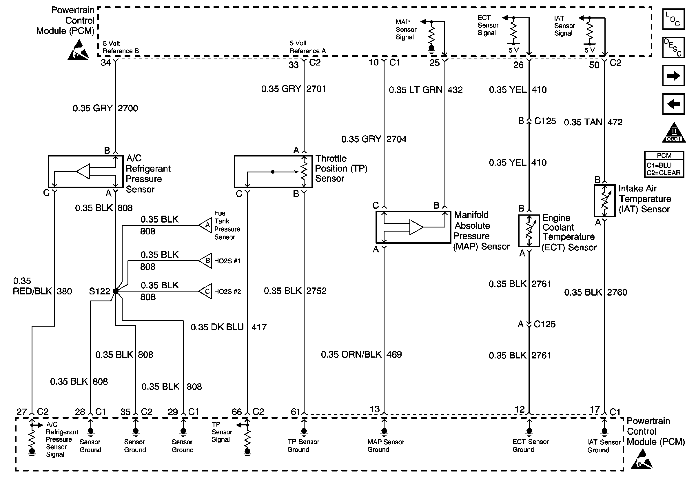
Refer to Engine Controls Schematics
A/C Pressure Switch, TPS, MAP, ECT and IAT
.
Circuit Description
The manifold absolute pressure (MAP) sensor is mounted to the top of the intake manifold. The MAP sensor measures pressure changes within the intake manifold which are an indication of engine load. The MAP sensor has a 5.0 volt reference, a ground, and a signal circuit.
The MAP sensor contains a diaphragm which changes resistance based on pressure. When manifold pressure is low, or the vacuum is high, sensor output voltage is low. When manifold pressure is high, or the vacuum is low, sensor output voltage is high. MAP sensor voltage, depending on altitude, can range from below 2 volts at idle to above 4 volts at wide open throttle (WOT) or with the engine not running.
The MAP sensor signal is also used at initial key-up to determine barometric pressure (BARO).
Conditions for Running the DTC
| • | No Throttle position (TP) sensor DTCs are present. |
| • | The ignition is ON. |
| • | The throttle angle is steadily below 2 percent if the engine speed is less than 900 RPM. |
Conditions for Setting the DTC
The MAP sensor intermittently indicates a voltage more than 4.2 volts.
Action Taken When the DTC Sets
| • | The powertrain control module (PCM) stores the DTC information into memory when the diagnostic runs and fails. |
| • | The malfunction indicator lamp (MIL) will not illuminate. |
| • | The PCM records the operating conditions at the time the diagnostic fails. The PCM stores this information in the Failure Records. |
Conditions for Clearing the MIL/DTC
| • | A History DTC will clear after 40 consecutive warm-up cycles, if no failures are reported by this or any other non-emission related diagnostic. |
| • | The current DTC will clear when the diagnostic runs and does not fail. |
| • | Use a scan tool in order to clear the MIL diagnostic trouble code. |
| • | Interrupting the PCM battery voltage may or may not clear DTCs. This practice is not recommended. Refer to Powertrain Control Module Description , Clearing Diagnostic Trouble Codes. |
Diagnostic Aids
Notice: Use the connector test adapter kit J 35616-A for any test that
requires probing the following items:
• The PCM harness connectors • The electrical center fuse/relay cavities • The component terminals • The component harness connector
Check for the following conditions:
| • | Poor connection at PCM or MAP sensor -- Inspect harness connectors for backed out terminals, improper mating, broken locks, improperly formed or damaged terminals, and poor terminal to wire connection. |
| • | Damaged harness -- Inspect the wiring harness for damage. If the harness appears to be OK, observe the MAP display on the scan tool while moving connectors and wiring harnesses related to the sensor. A change in the display will indicate the location of the malfunction. |
Reviewing the Failure Records vehicle mileage since the diagnostic test last failed may help determine how often the condition that caused the DTC to be set occurs. This may assist in diagnosing the condition.
If the problem is intermittent, refer to Intermittent Conditions .
Step | Action | Values | Yes | No | ||||||
|---|---|---|---|---|---|---|---|---|---|---|
1 | Did you perform the Powertrain On-Board Diagnostic (OBD) System Check? | -- | ||||||||
2 | Select DTC info, Last Test Fail and note any other DTCs set. Is DTC P0108 also set? | -- | Go to DTC P0108 Manifold Absolute Pressure (MAP) Sensor Circuit High Voltage . | |||||||
3 | Is DTC P1111, P1115, and/or P1121 also set? | -- | ||||||||
4 | Check for a poor sensor ground circuit terminal connection at the MAP sensor. Refer to Wiring Repairs in Wiring Systems. Was a problem found? | -- | ||||||||
5 | Check the MAP signal circuit between the MAP sensor connector and the PCM for an intermittent short to voltage. Refer to Wiring Repairs in Wiring Systems. Was a problem found? | -- | ||||||||
6 | Check for an intermittent short to voltage on the 5 volt reference A circuit between the PCM and the following components:
Refer to Testing for Intermittent Conditions and Poor Connections or Refer to Wiring Repairs in Wiring Systems. Was a problem found? | -- | ||||||||
7 | Check for a poor sensor ground circuit terminal connection at the PCM. Was a problem found? | -- | ||||||||
8 | Check for an intermittent open in the sensor ground circuit. Was a problem found? | -- | Go to Diagnostic Aids | |||||||
9 | Replace the malfunctioning harness connector terminal for the sensor ground circuit. Refer to Connector Repairs , or Testing for Intermittent Conditions and Poor Connections in Wiring Systems. Is the action complete? | -- | -- | |||||||
10 | Locate and repair intermittent open or short circuit in wiring harness as necessary. Refer to Testing for Intermittent Conditions and Poor Connections or Refer to Wiring Repairs in Wiring Systems. Is the action complete? | -- | -- | |||||||
11 |
Does the scan tool indicate that this test ran and passed? | -- | ||||||||
12 | Review Captured Info using the scan tool. Are there any DTCs that have not been diagnosed? | -- | Go to the applicable DTC table | System OK |
