Battery Cable Replacement Positive, 3.5L Twin Cam V6 LX5
Removal Procedure
Caution: Unless directed otherwise, the ignition and start switch must be in the OFF or LOCK position, and all electrical loads must be OFF before servicing any electrical component. Disconnect the negative battery cable to prevent an electrical spark should a tool or equipment come in contact with an exposed electrical terminal. Failure to follow these precautions may result in personal injury and/or damage to the vehicle or its components.
Caution: This vehicle is equipped with a Supplemental Inflatable Restraint (SIR) System. Failure to follow the correct procedure could cause the following conditions:
• Air bag deployment • Personal injury • Unnecessary SIR system repairs • Refer to SIR Component Views in order to determine if you are performing service on or near the SIR components or the SIR wiring. • If you are performing service on or near the SIR components or the SIR wiring, disable the SIR system. Refer to Disabling the SIR System.
When replacing battery cables be sure to use replacement cables that are the same type, gauge and length.
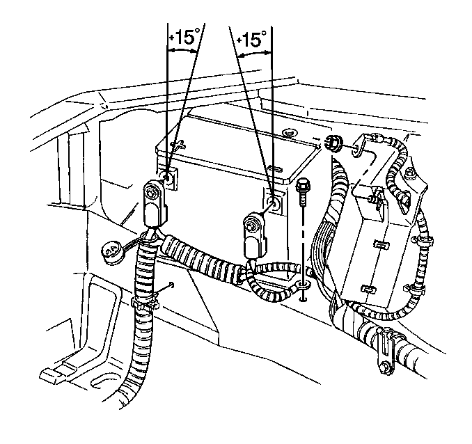
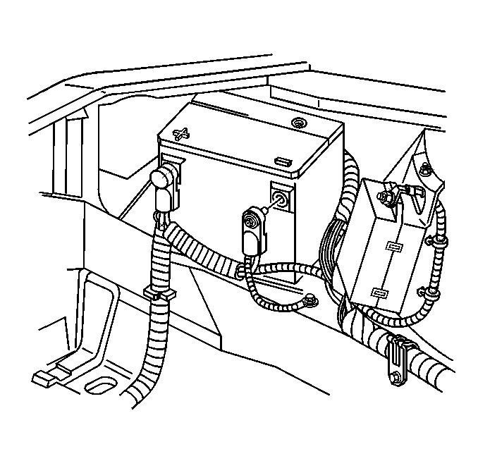
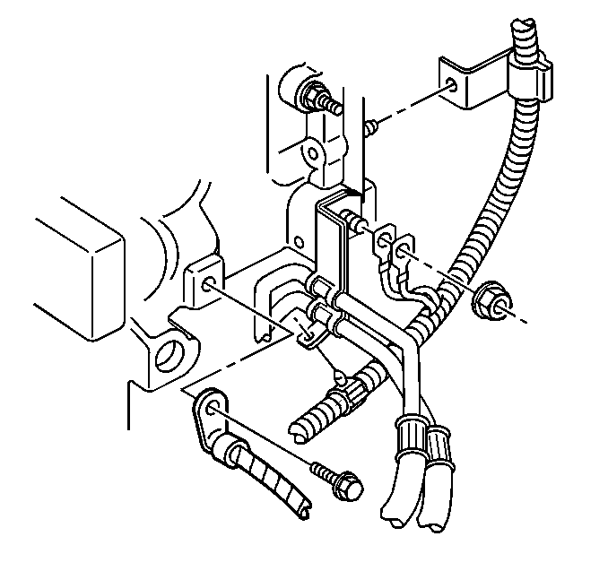
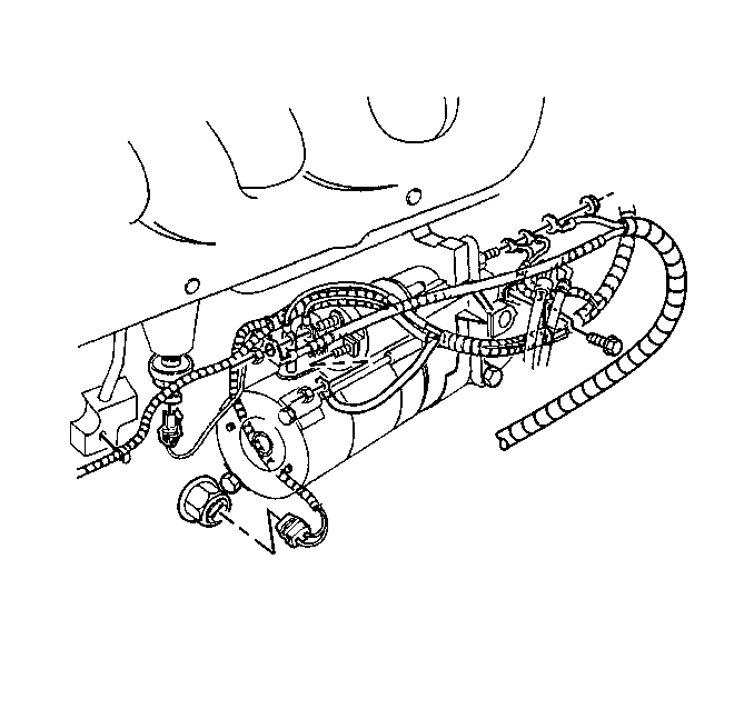
- Disconnect the battery ground (negative) cable from the battery. Refer to Battery Negative Cable Disconnection and Connection .
- Disconnect the battery (positive) cable from the battery.
- Remove the remote positive stud cover.
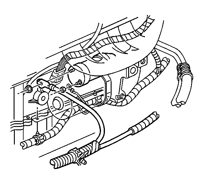
- Remove the battery (positive) cable junction block lead nut, the engine harness lead, and the battery (positive) cable from the underhood accessory wiring junction block.
- Remove the battery (positive) cable from the starter motor BAT terminal.
- Remove the battery cable retainers from the engine frame.
- Remove the battery (positive) cable from the wiring harness conduit.

Installation Procedure
- Install the battery (positive) cable into the wiring harness conduit.
- Install the battery cable retainers to the engine frame.
- Install the battery (positive) cable to the starter motor BAT terminal.
- Install the starter solenoid BAT terminal nut.
- Install the battery (positive) cable, the engine harness lead, and the battery (positive) cable junction block lead nut to the underhood accessory wiring junction block.
- Install the remote positive stud cover.
- Install the battery (positive) cable to the battery.
- Connect the battery ground (negative) cable to the battery. Refer to Battery Negative Cable Disconnection and Connection .
Notice: Use the correct fastener in the correct location. Replacement fasteners must be the correct part number for that application. Fasteners requiring replacement or fasteners requiring the use of thread locking compound or sealant are identified in the service procedure. Do not use paints, lubricants, or corrosion inhibitors on fasteners or fastener joint surfaces unless specified. These coatings affect fastener torque and joint clamping force and may damage the fastener. Use the correct tightening sequence and specifications when installing fasteners in order to avoid damage to parts and systems.
Tighten
Tighten the starter solenoid BAT terminal nut to 10 N·m
(84 lb in).
Tighten
Tighten the battery (positive) cable junction block lead nut to 10 N·m
(89 lb in).
Tighten
Tighten the battery (positive) cable terminal bolt to 15 N·m
(11 lb ft).
Battery Cable Replacement Ground, 3.5L Twin Cam V6 LX5
Removal Procedure
Caution: Unless directed otherwise, the ignition and start switch must be in the OFF or LOCK position, and all electrical loads must be OFF before servicing any electrical component. Disconnect the negative battery cable to prevent an electrical spark should a tool or equipment come in contact with an exposed electrical terminal. Failure to follow these precautions may result in personal injury and/or damage to the vehicle or its components.
Caution: This vehicle is equipped with a Supplemental Inflatable Restraint (SIR) System. Failure to follow the correct procedure could cause the following conditions:
• Air bag deployment • Personal injury • Unnecessary SIR system repairs • Refer to SIR Component Views in order to determine if you are performing service on or near the SIR components or the SIR wiring. • If you are performing service on or near the SIR components or the SIR wiring, disable the SIR system. Refer to Disabling the SIR System.
When replacing battery cables be sure to use replacement cables that are the same type, gauge and length.
- Disconnect the battery ground (negative) cable from the battery. Refer to Battery Negative Cable Disconnection and Connection .
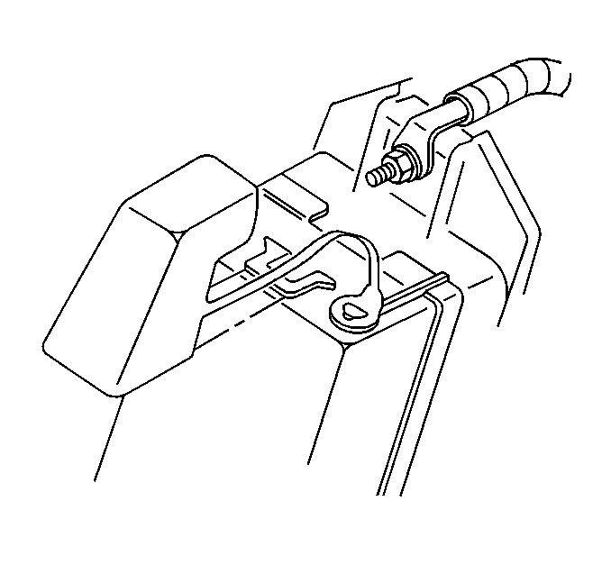
- Remove the battery negative cable screw and the battery ground (negative) cable from the frame rail near the underhood accessory wiring junction block.
- Remove the transaxle stud nut and the battery ground (negative) cable from the transaxle stud.
- Remove the battery cable retainers from the engine frame.
- Remove the battery ground (negative) cable from the wiring harness conduit.
Installation Procedure
- Install the battery ground (negative) cable into the wiring harness conduit.
- Install the battery cable retainers to the engine frame.
- Install the battery ground (negative) cable and the transaxle stud nut to the transaxle stud.
- Connect the battery ground (negative) cable and the battery negative cable screw to the frame rail near the underhood accessory wiring junction block.
- Connect the battery ground (negative) cable to the battery. Refer to Battery Negative Cable Disconnection and Connection .
Notice: Use the correct fastener in the correct location. Replacement fasteners must be the correct part number for that application. Fasteners requiring replacement or fasteners requiring the use of thread locking compound or sealant are identified in the service procedure. Do not use paints, lubricants, or corrosion inhibitors on fasteners or fastener joint surfaces unless specified. These coatings affect fastener torque and joint clamping force and may damage the fastener. Use the correct tightening sequence and specifications when installing fasteners in order to avoid damage to parts and systems.
Tighten
Tighten the transaxle stud nut to 25 N·m (18 lb ft).
Tighten
Tighten the battery negative cable screw to 8 N·m (71 lb in).
Tighten
Tighten the battery ground (negative) cable terminal bolt to 15 N·m
(11 lb ft).
Battery Cable Replacement Positive, 3800 V6 L36
Removal Procedure
Caution: Before servicing any electrical component, the ignition and start switch must be in the OFF or LOCK position and all electrical loads must be OFF, unless instructed otherwise in these procedures. If a tool or equipment could easily come in contact with a live exposed electrical terminal, also disconnect the negative battery cable. Failure to follow these precautions may cause personal injury and/or damage to the vehicle or its components.
Caution: This vehicle is equipped with a Supplemental Inflatable Restraint (SIR) System. Failure to follow the correct procedure could cause the following conditions:
• Air bag deployment • Personal injury • Unnecessary SIR system repairs • Refer to SIR Component Views in order to determine if you are performing service on or near the SIR components or the SIR wiring. • If you are performing service on or near the SIR components or the SIR wiring, disable the SIR system. Refer to Disabling the SIR System.
When replacing battery cables be sure to use replacement cables that are the same type, gauge and length.
- Disconnect the battery ground (negative) cable from the battery. Refer to Battery Negative Cable Disconnection and Connection .
- Disconnect the battery (positive) cable from the battery.
- Remove the remote positive stud cover.
- Remove the battery (positive) cable junction block lead nut and battery (positive) cable from the underhood accessory wiring junction block.
- Raise and suitably support the vehicle. Refer to Lifting and Jacking the Vehicle in General Information.
- Remove the battery (positive) cable from the starter motor BAT terminal.
- Remove the battery cable retainers from the engine frame.
- Remove the battery (positive) cable from the wiring harness conduit.
Installation Procedure
- Install the battery (positive) cable into the wiring harness conduit.
- Install the battery cable retainers to the engine frame.
- Install the battery (positive) cable to the starter motor BAT terminal.
- Install the starter solenoid BAT terminal nut.
- Lower the vehicle.
- Install the battery (positive) cable junction block lead nut and battery (positive) cable to the underhood accessory wiring junction block.
- Install the remote positive stud cover.
- Install the battery (positive) cable to the battery.
- Connect the battery ground (negative) cable to the battery. Refer to Battery Negative Cable Disconnection and Connection .
Notice: Use the correct fastener in the correct location. Replacement fasteners must be the correct part number for that application. Fasteners requiring replacement or fasteners requiring the use of thread locking compound or sealant are identified in the service procedure. Do not use paints, lubricants, or corrosion inhibitors on fasteners or fastener joint surfaces unless specified. These coatings affect fastener torque and joint clamping force and may damage the fastener. Use the correct tightening sequence and specifications when installing fasteners in order to avoid damage to parts and systems.
Tighten
Tighten the starter solenoid BAT terminal nut to 10 N·m
(84 lb in).
Tighten
Tighten the battery (positive) cable junction block lead nut to 10 N·m
(89 lb in).
Tighten
Tighten the battery (positive) cable terminal bolt to 15 N·m
(11 lb ft).
Battery Cable Replacement Ground, 3800 V6 L36
Removal Procedure
Caution: Before servicing any electrical component, the ignition and start switch must be in the OFF or LOCK position and all electrical loads must be OFF, unless instructed otherwise in these procedures. If a tool or equipment could easily come in contact with a live exposed electrical terminal, also disconnect the negative battery cable. Failure to follow these precautions may cause personal injury and/or damage to the vehicle or its components.
Caution: This vehicle is equipped with a Supplemental Inflatable Restraint (SIR) System. Failure to follow the correct procedure could cause the following conditions:
• Air bag deployment • Personal injury • Unnecessary SIR system repairs • Refer to SIR Component Views in order to determine if you are performing service on or near the SIR components or the SIR wiring. • If you are performing service on or near the SIR components or the SIR wiring, disable the SIR system. Refer to Disabling the SIR System.
When replacing battery cables be sure to use replacement cables that are the same type, gauge and length.
- Disconnect the battery ground (negative) cable from the battery. Refer to Battery Negative Cable Disconnection and Connection .
- Remove the battery negative cable screw and the battery ground (negative) cable from the frame rail near the underhood accessory wiring junction block.
- Remove the transaxle stud nut and the battery ground (negative) cable from the transaxle stud.
- Remove the battery cable retainers from the engine frame.
- Remove the battery ground (negative) cable from the wiring harness conduit.
Installation Procedure
- Install the battery ground (negative) cable into the wiring harness conduit.
- Install the battery cable retainers to the engine frame.
- Install the battery ground (negative) cable and the transaxle stud nut to the transaxle stud.
- Connect the battery ground (negative) cable and the battery negative cable screw to the frame rail near the underhood accessory wiring junction block.
- Connect the battery ground (negative) cable to the battery. Refer to Battery Negative Cable Disconnection and Connection .
Notice: Use the correct fastener in the correct location. Replacement fasteners must be the correct part number for that application. Fasteners requiring replacement or fasteners requiring the use of thread locking compound or sealant are identified in the service procedure. Do not use paints, lubricants, or corrosion inhibitors on fasteners or fastener joint surfaces unless specified. These coatings affect fastener torque and joint clamping force and may damage the fastener. Use the correct tightening sequence and specifications when installing fasteners in order to avoid damage to parts and systems.
Tighten
Tighten the transaxle stud nut to 25 N·m (18 lb ft).
Tighten
Tighten the battery negative cable screw to 8 N·m (71 lb in).
Tighten
Tighten the battery ground (negative) cable terminal bolt to 15 N·m
(11 lb ft).
