Engine Coolant Thermostat Replacement 3800 V6 L36
Removal Procedure
Tools Required
J 38185 Hose Clamp Pliers
- Remove the fuel injector sight shield. Refer to Fuel Injector Sight Shield Replacement in Engine Mechanical.
- Remove the throttle body air inlet duct. Refer to Air Cleaner Assembly Replacement in Engine Controls .
- Partially drain the engine coolant from the cooling system. Refer to Cooling System Draining and Filling .
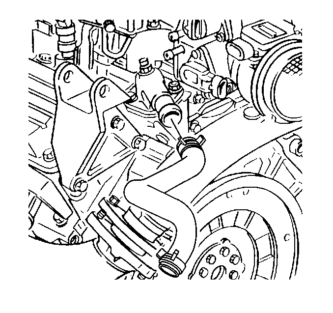
- Use the J 38185 in order to remove the radiator hose clamp from the water outlet housing.
- Disconnect the radiator hose from the water outlet housing.
- Remove the water outlet housing bolts.
- Remove the water outlet housing and gasket.
- Remove the thermostat.
- Inspect and clean the mating surfaces.
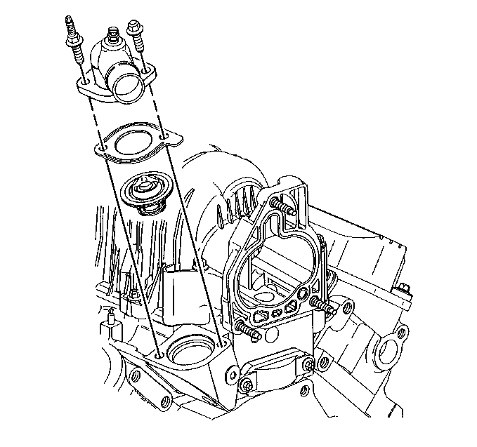
| • | Water outlet housing |
| • | Lower intake manifold |
Installation Procedure
Tools Required
J 38185 Hose Clamp Pliers
NOTICE: When adding coolant, it is important that you use GM Goodwrench DEX-COOL® or HAVOLINE® DEX-COOL® coolant. If Coolant other than DEX-COOL® or HAVOLINE® DEX-COOL® is added to the system the engine coolant will require change sooner; at 50 000 km (30,000 mi) or 24 months.
- Install the thermostat.
- Install the gasket and water outlet housing.
- Install the water outlet housing bolts with RTV Sealer GM P/N 1052366 or equivalent.
- Connect the radiator hose to the water outlet housing.
- Use theJ 38185 in order to install the radiator hose clamp to the water outlet housing.
- Fill the cooling system with engine coolant. Refer to Cooling System Draining and Filling .
- Install the throttle body air inlet duct. Refer to Air Cleaner Assembly Replacement in Engine Controls.
- Install the fuel injector sight shield. Refer to Fuel Injector Sight Shield Replacement in Engine Mechanical.
- Inspect for leaks.

Notice: Use the correct fastener in the correct location. Replacement fasteners must be the correct part number for that application. Fasteners requiring replacement or fasteners requiring the use of thread locking compound or sealant are identified in the service procedure. Do not use paints, lubricants, or corrosion inhibitors on fasteners or fastener joint surfaces unless specified. These coatings affect fastener torque and joint clamping force and may damage the fastener. Use the correct tightening sequence and specifications when installing fasteners in order to avoid damage to parts and systems.
Tighten
Tighten the water outlet housing bolts to 27 N·m (20 lb ft).

Engine Coolant Thermostat Replacement 3.5L V6 LX5
Removal Procedure
Tools Required
J 38185 Hose Clamp Pliers
- Partially drain the engine coolant from the cooling system. Refer to Cooling System Draining and Filling .
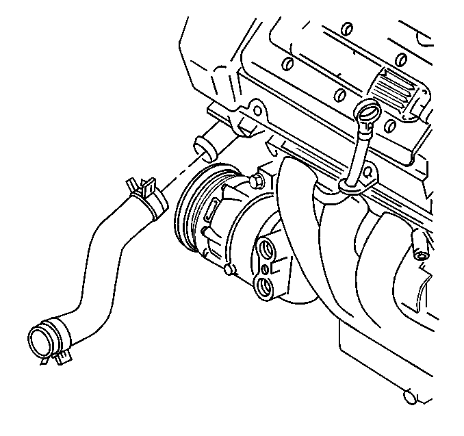
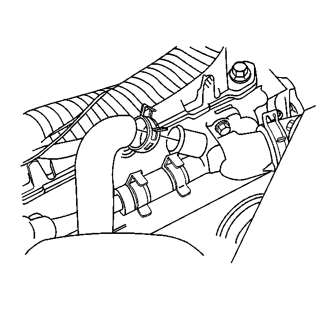
- Use theJ 38185 in order to remove the radiator hose clamp to the water inlet housing.
- Disconnect the radiator hose from the water inlet housing.
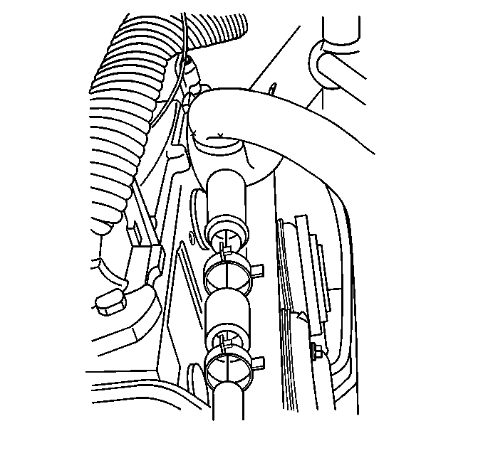
- Remove the heater hose clamp from the water inlet housing using the J 38185 .
- Disconnect the heater hose from the water inlet housing.
- Remove the surge tank inlet hose clamp from the water inlet housing using the J 38185 .
- Disconnect the surge tank inlet hose from the water inlet housing.
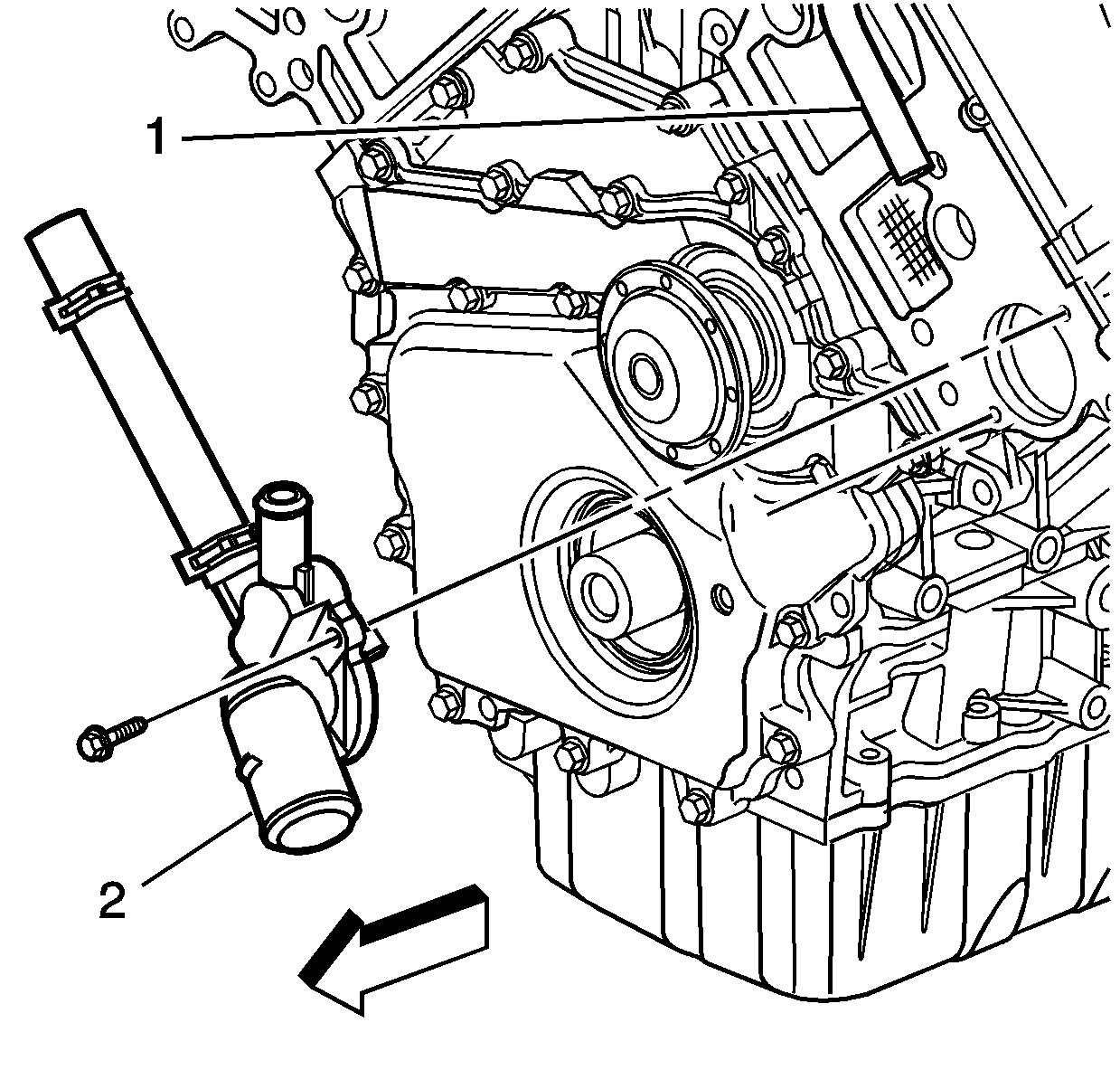
- Remove the water inlet housing bolts.
- Remove the water inlet housing.
- Inspect and clean the mating surfaces for the following components:
- Replace inlet housing and thermostat as an assembly.
Installation Procedure
- Install the water inlet housing and thermostat assembly.
- Install the water housing bolts with RTV Sealer GM P/N 1052366 or equivalent.
- Connect the surge tank inlet hose to the water inlet housing.
- Use theJ 38185 in order to install the surge tank hose clamp to the water inlet housing.
- Connect the heater hose to the water inlet housing.
- Use theJ 38185 in order to install the heater hose clamp to the water inlet housing.
- Connect the radiator hose to the water inlet housing.
- Use theJ 38185 in order to install the radiator hose clamp to the water inlet housing.
- Fill the cooling system with engine coolant. Refer to Cooling System Draining and Filling .
- Inspect for leaks.

NOTICE: When adding coolant, it is important that you use GM Goodwrench DEX-COOL® or HAVOLINE® DEX-COOL® coolant. If Coolant other than DEX-COOL® or HAVOLINE® DEX-COOL® is added to the system the engine coolant will require change sooner; at 50 000 km (30,000 mi) or 24 months.
Notice: Use the correct fastener in the correct location. Replacement fasteners must be the correct part number for that application. Fasteners requiring replacement or fasteners requiring the use of thread locking compound or sealant are identified in the service procedure. Do not use paints, lubricants, or corrosion inhibitors on fasteners or fastener joint surfaces unless specified. These coatings affect fastener torque and joint clamping force and may damage the fastener. Use the correct tightening sequence and specifications when installing fasteners in order to avoid damage to parts and systems.
Tighten
Tighten the water inlet housing bolts to 9 N·m (80 lb in).


