ELECT. SYSTEM MAN. UPDATE SEC 8A (ELECT. DIAGNOSIS REVISION)

SUBJECT: ELECTRICAL SYSTEMS/ SMU SECTION 8A - ELECTRICAL DIAGNOSIS REVISIONS
VEHICLES AFFECTED: 1992 "H" MODELS -----------------------------------------------------------------------------
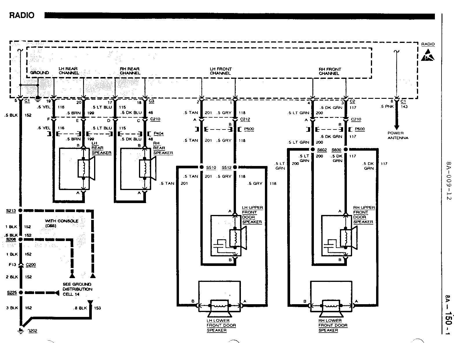
The following "UPDATE CHANGE SUMMARY" reflects changes and revisions to Electrical Diagnosis Procedures in the Service Manual- Section 8A.
Please update your Service Manual Accordingly.
CARLINE: PONTIAC BONNEVILLE SE ------------------------------
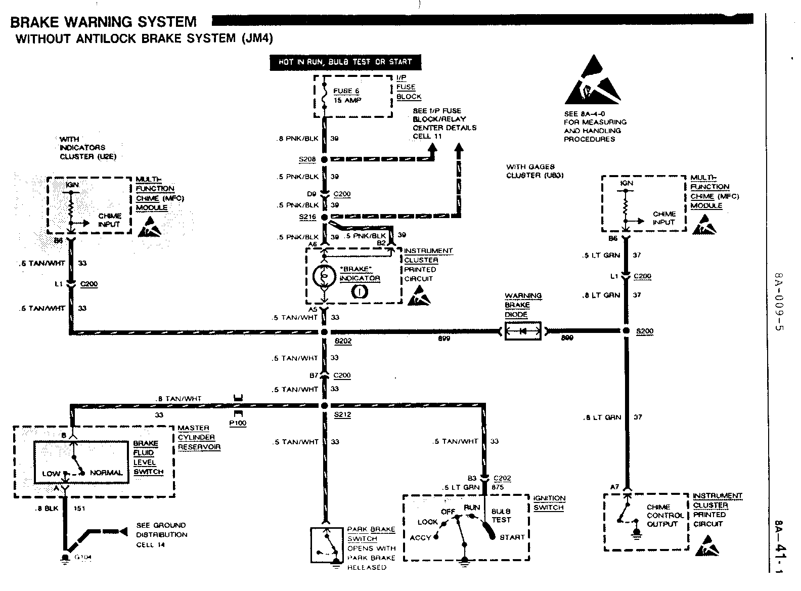
Page(s) Revision ------ -------- 8A-44-2, The .5 TAN (800) wires at terminal 42 of the Electronic Brake 8A-47-0, Control Module (EBCM), terminal A8 of the Diagnostic/Energy 8A-50-0 Reserve Module (DERM), and at terminals C and H of connector C2 of the Remote Accessory (RAC) Control Module is changed to .8 TAN (800).
8A-45-0 The .5 BLK (1387) wire at the TFE Steering Solenoid is changed to .5 DK GRN/WHT (1387).
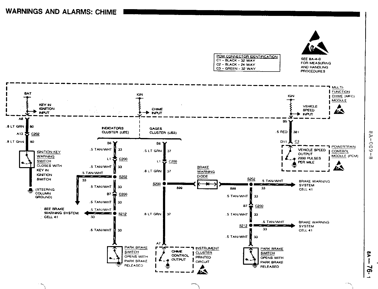
8A-45-0, The .8 BLK (1387) wire between terminal B8 of the 8A-76-0 Multi-Function Chime (MFC) Module and terminal E1 of connector C260 is changed to .8 DK GRN/WHT (1387).
8A-64-0 The .8 DK GRN/YEL (762) wire between in-line connector C200 and the A/C High Pressure Cut-Out Switch is changed to 1 LT GRN (66).
8A-64-0 The .8 DK BLU (204) wire at terminal B of the A/C High Pressure Cut-Out Switch is changed to 1 DK BLU (204).
8A-112-0 The .5 RED (1324) wires to the Tail/Back Up Light Assemblies are changed to .8 LT GRN (24).
8A-115-0 The terminal at in-line connectors C701 and C801 between the Rear Door Courtesy Lights and Splice S211 is changed to C.
CARLINE: PONTIAC BONNEVILLE SE ------------------------------
Page(s) Revision ------- --------- 8A-10-1, The 3 RED (1441) wires between Fuse 6 and terminal F of 8A-12-0, connector C1 of the Head/Park Light Switch is changed to 5 RED 8A-101-0 (1441).
8A-10-2, The .8 ORN (440) wires between terminal H8 of connector C260 8A-20-0 and the Powertrain Control Module (PCM) are changed to 1 ORN (440).
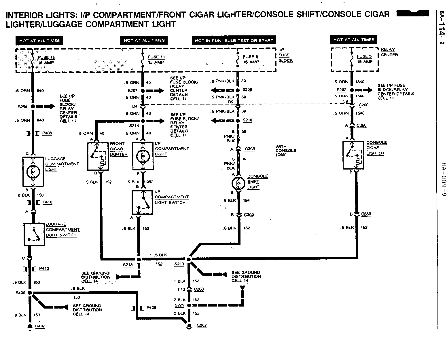
8A-11-4, The .8 ORN (40) wires at splice S207 (Power Feed For 8A-76-0, Multi-Function Chime (MFC) Module and Oil Level Module) are 8A-80-2, changed to .5 ORN (40). 8A-81-2
8A-11-6, Change the .5 BRN (250) wires at splice S104 to .35 BRN (250). 8A-20-5, 8A-31-0
8A-14-1, The .5 BLK (151) wire in terminal B of connector C2 of the LH 8A-100-0, Composite Headlight Assembly is changed to .8 BLK (151). 8A-101-1
8A-14-2, The .8 wires to the Blower Resistor Assembly and the Blower 8A-63-0 Relay are changed to 1.
8A-14-2, The 1 BLK (155) wire at the RH Fog Light is changed to .8 BLK 8A-100-1, (155). 8A-101-2
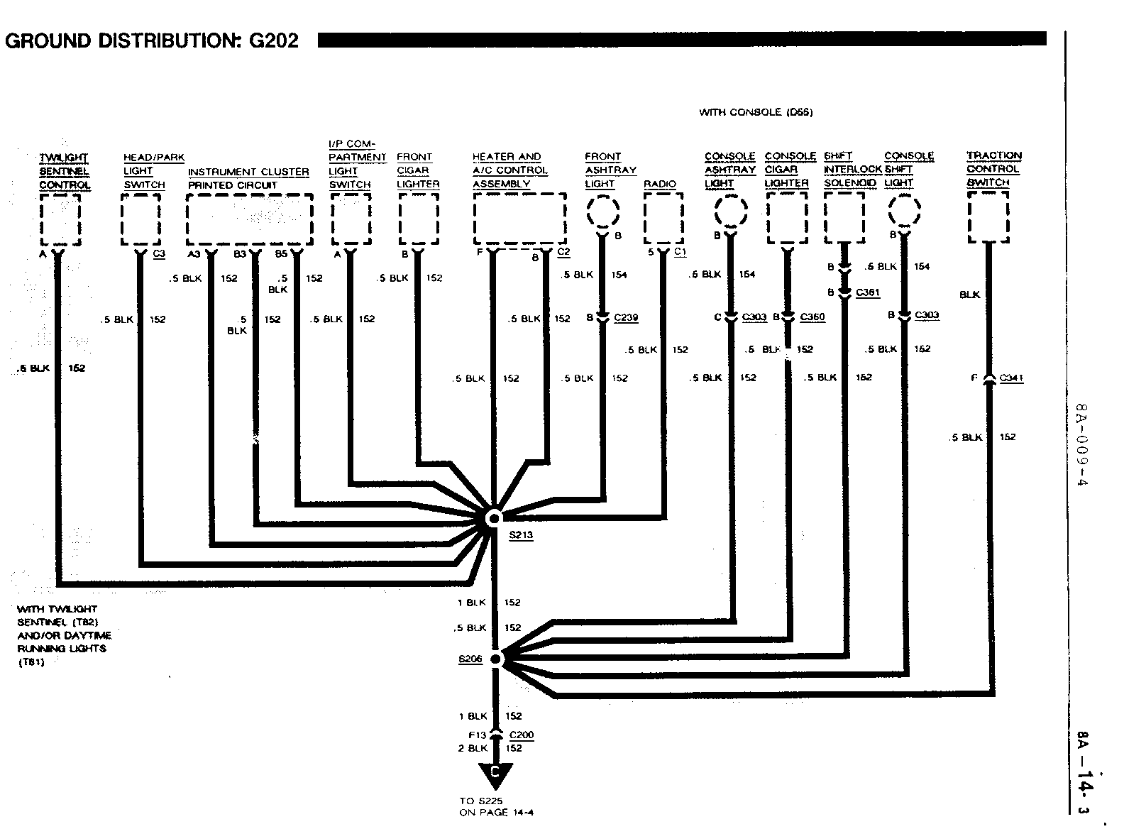
8A-14-4 The .8 BLK (1 52) wire between splice S225 and in-line connector C205 is changed to .5 BLK (1 52).
8A-20-3, The .5 YEL (400) wire between terminal D14 of connector C3 of 8A-33-0, the Powertrain Control Module (PCM) and terminal P9 of in- 8A-34-1 line connector C260 is changed to .35 YEL (400).
8A-20-5, The .35 BRN (86) wire between the Cruise/Shift Interlock/Brake 8A-34-0 Switch and terminal D10 of connector C1 of the Powertrain Control Module (PCM) is changed to .5 BRN (86).
CARLINE: BUICK LESABRE ----------------------
Page(s) Revision ------- -------- 18, 62 The .8 ORN (440) wires between terminal H8 of connector C265 and the Powertrain Control Module (PCM) are changed to 1 ORN (440).
28, 158 The in-line connector between Fuse 17 and the ELC Height Sensor terminal G12 of C200 is changed to G2 of C200.
33, 206 The .5 BLK (151) wire in terminal B of Connector C2 of the LH Composite Headlight Assembly is changed to .8 BLK (151).
34, 350 The .8 BLK (155) wire in terminal 5 of the High Speed Blower Relay is changed to 1 BLK (155).
40, 120 The .5 TAN (800) wires at terminal 42 of the Electronic Brake Control Module (EBCM), terminal A8 of the Diagnostic/Energy Reserve Module (DERM), and at terminals C and H of connector C2 of the Remote Accessory Control (RAC) Module is changed to .8 TAN (800).
64, 84 The .35 BRN (86) wire between the Cruise/Shift Interlock/Brake Switch and terminal D10 of connector C1 of the Powertrain Control Module (PCM) is changed to .5 BRN (86).
65, 78, 84 The .5 YEL (400) wire between terminal D14 of connector C3 of the Powertrain Control Module (PCM) and in-line connector C265 terminal P9 is changed to .35 YEL (400).
84 The in-line connector between the Cruise Indicator (indicators Cluster) and terminal D1 of connector C3 of the Powertrain Control Module (PCM), which was formerly terminal J10 of C200, is changed to J10 of C200 with C67 and E2 of C200 with CJ2.
194, 261 The in-line connector between the Security Indicator and terminal A5 of the Pass Key Decoder Module is now J9 of C200 to J9 of C200 with C67 or E13 with CJ2 of C200.
232 The terminal at in-line connectors C701 and C801 between the Rear Door Lights and Splice S252 is changed to C.
350 The .8 DK GRN/YEL (762) wire between terminal A of the A/C High Pressure Cut-Out Switch and terminal F2 of in-line connector C265 is changed to 1 LT GRN (66).
350 The .8 DK BLU (204) wire at terminal B of the A/C High Pressure Cut-Out Switch is changed to 1 DK BLU (204).
CARLINE: OLDSMOBILE EIGHTY-EIGHT ROYALE ---------------------------------------
Page(s) Revision ------- -------- 8A-10-1, Change the 3 RED (1441) wires between Fuse 6 and terminal C of 8A-12-0, the Head/Park Light Switch to 5 RED (1441). 8A-101-0
8A-10-2, The .8 ORN (440) wires between terminal H8 of connector C260 8A-20-0 and the Powertrain Control Module (PCM) are changed to 1 ORN (440).
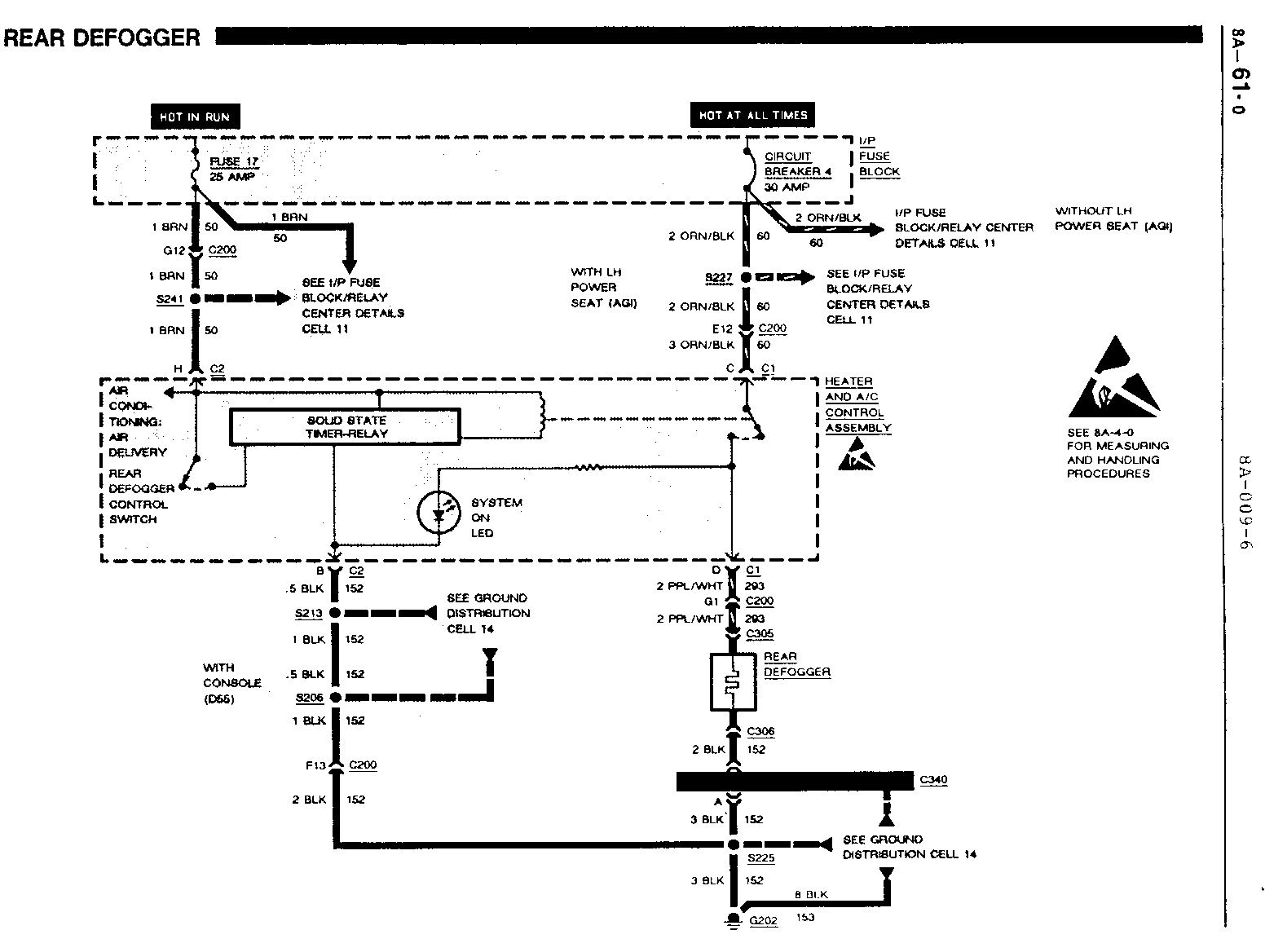
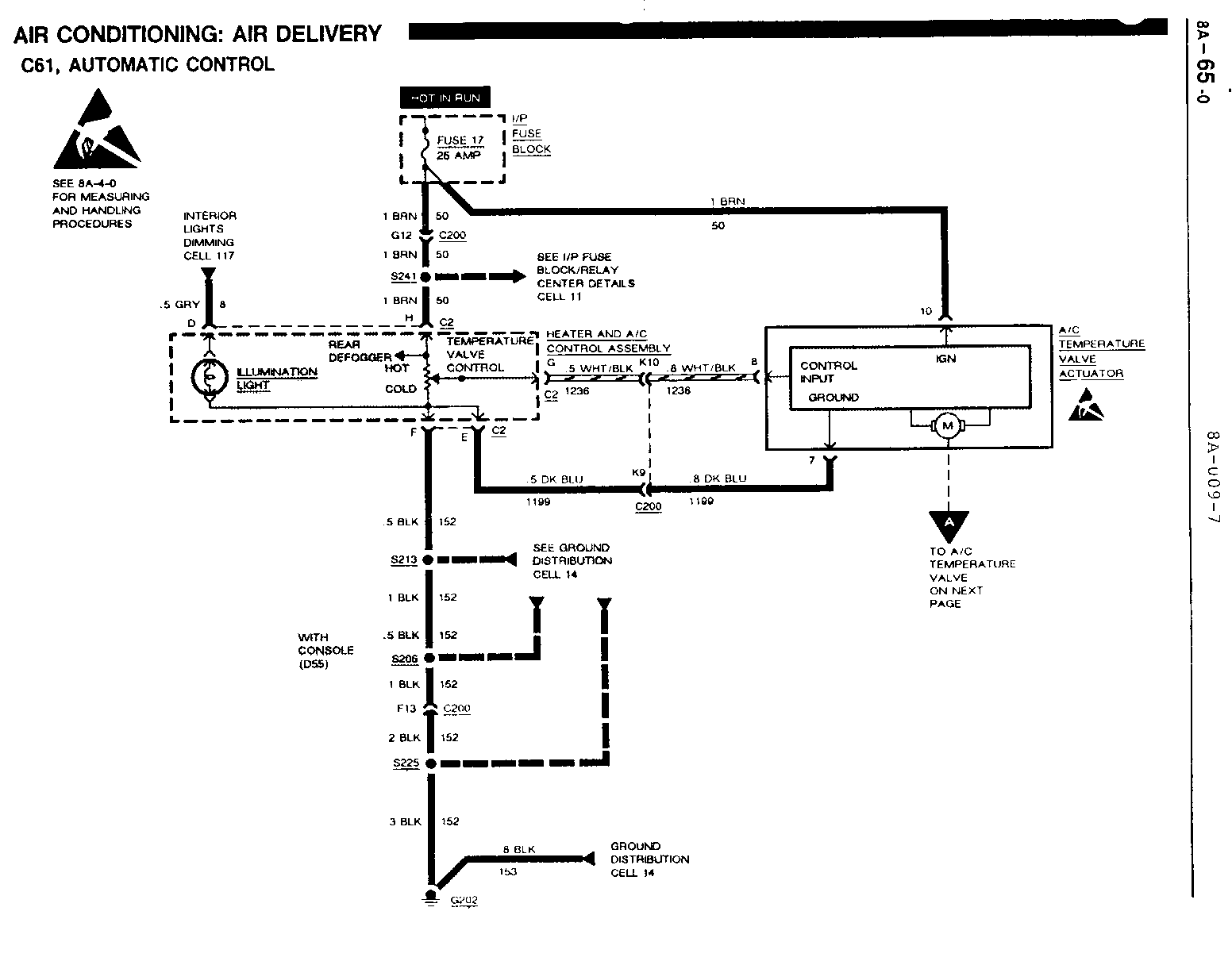
8A-11-5, Change all .5 BRN (50) wires at Splice S241 to 1 BRN (50). 8A-42-0 8A-61-0, 8A-63-0, 8A-64-0, 8A-65-0, 8A-68-0, 8A-80-3, 8A-82-2, 8A-82-3, 8A-82-5
8A-12-0, The .5 BRN (9) wires at the Front Side Marker Lights are 8A-110-1 changed to .8 BRN (9).
8A-14-2 The .8 BLK (155) ground wire between the Blower Relay and S109 has been changed to 1.
8A-63-0, The .8 wires to the Blower Resistor Assembly and the Blower 8A-63-1 Relay are changed to 1.
8A-64-0, The .8 DK GRN/YEL (762) wires between in-line connectors C200 8A-67-0 (C61) or C260 (C68) and the A/C High Pressure Cut-Out Switch is changed to 1 LT GRN (66).
8A-64-0 The .8 DK BLU (204) wire at terminal B of the A/C High Pressure Cut-Out Switch is changed to 1 DK BLU (204).
8A-110-3 The .5 BRN/WHT (I 253) wires to the Front Side Marker Lights are changed to .8 BRN/WHT (1253).
General Motors bulletins are intended for use by professional technicians, not a "do-it-yourselfer". They are written to inform those technicians of conditions that may occur on some vehicles, or to provide information that could assist in the proper service of a vehicle. Properly trained technicians have the equipment, tools, safety instructions and know-how to do a job properly and safely. If a condition is described, do not assume that the bulletin applies to your vehicle, or that your vehicle will have that condition. See a General Motors dealer servicing your brand of General Motors vehicle for information on whether your vehicle may benefit from the information.
