SERVICE MANUAL UPDATE SEC. 8A ELECTRICAL DIAG. REVISION

SUBJECT: ELECTRICAL DIAGNOSIS REVISIONS
MODELS/YEARS: 1992 EIGHTY EIGHT AND EIGHTY EIGHT
The following "UPDATE CHANGE SUMMARY" and revised pages reflect changes and revisions to Electrical Diagnostic Procedures in the 1992 Eighty Eight Service Manual, Section 8A. Please update your service manual accordingly. See pages 4-8 of this bulletin for 1992 Ninety Eight Revisions.
PAGES REVISION
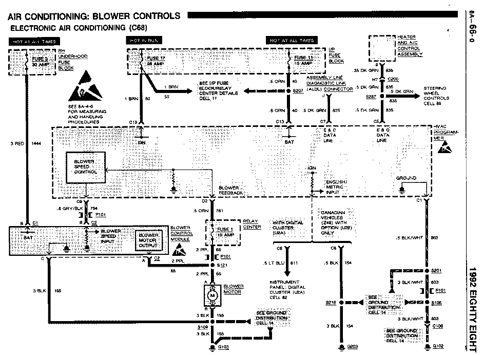
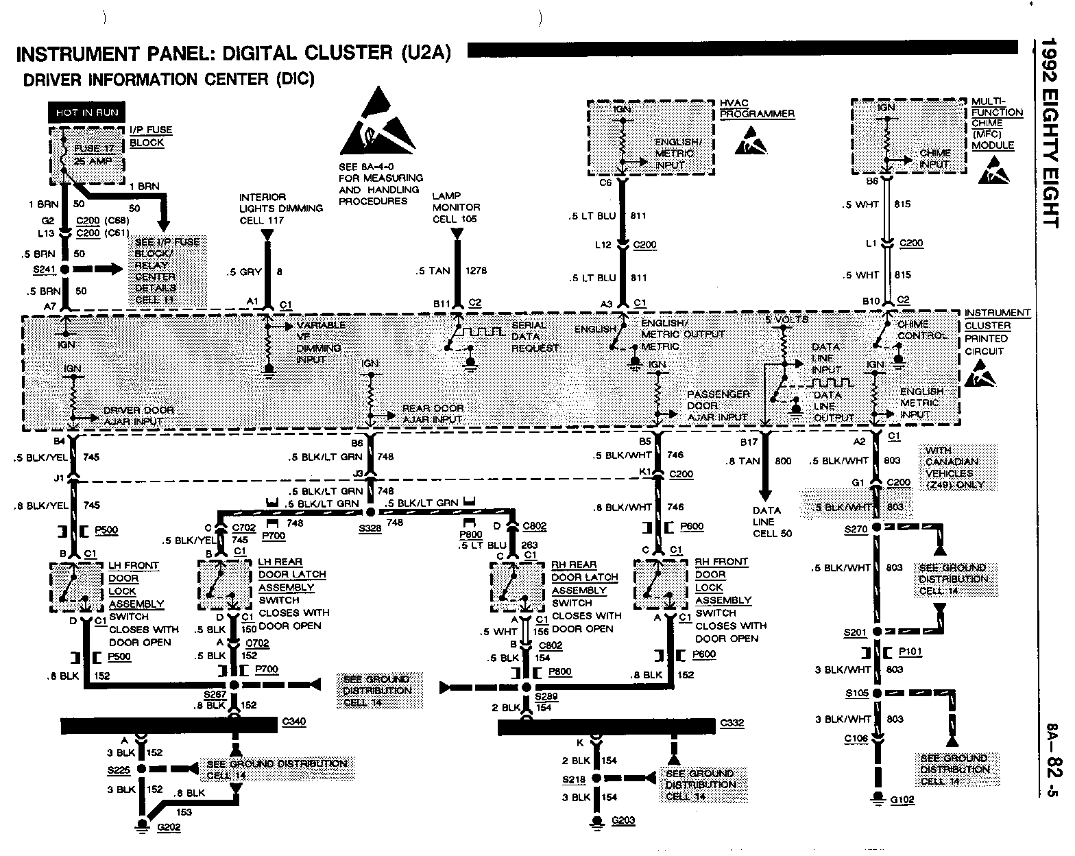
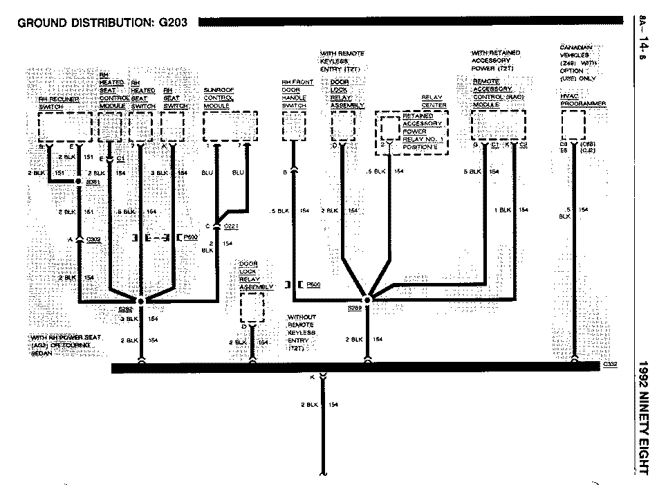
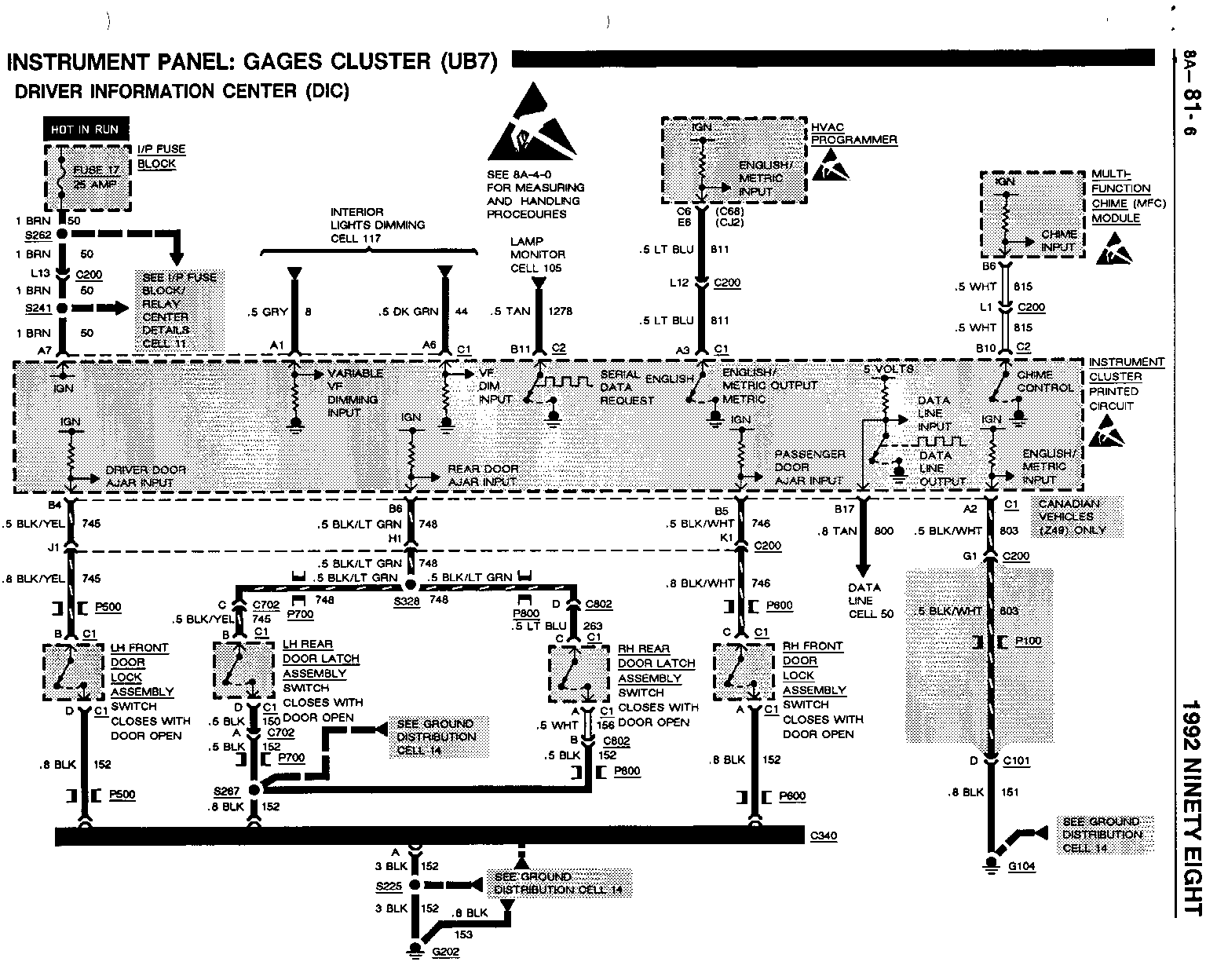
8A-10-1, Change the 3 RED (1441) wires between Fuse 6 and terminal C of the Head/Park Switch to 5 8A-12-0 RED (1441). 8A-10-2, The 0.8 ORN (440) wires between terminal H8 of connector C260 and the Powertrain Control 8A-20-0 Module (PCM) are changed to 1 ORN (440). 8A-11-5, Change all 0.5 BRN (50) wires at Splice S241 to I BRN (50). 8A-42-0, 8A-61-0, 8A-63-0, 8A-64-0, 8A-65-0, 8A-68-0, 8A-80-3, 8A-82-2, 8A-82-3, 8A-12-0, The 0.5 BRN (50) wires at the Front Side Marker Lights are changed to 0.8 BRN (9). 8A-110-1 8A-14-7 Change the qualifier "CANADIAN MODELS (Z49) WITH ELECTRONIC AIR CONDITIONING (C68)" to "CANADIAN VEHICLES (Z49) WITH OPTION (U2E) ONLY. 8A-14-2 The 0.8 BLK (155) ground wire between the Blower Relay and S109 has been changed to 1. 8A-63-0, The 0.8 wires to the Blower Resistor Assembly and the Blower Relay are changed to 1. 8A-63-1 8A-65-0 Change terminals 9 of the A/C Temperature Valve Actuator to terminal 8. 8A-64-0, The 0.8 DK GRN/YEL (762) wires between in-line connectors C200 (C61) or C269 (C68) and 8A-67-0 the A/C High Pressure Cut-Out Switch is changed to 1 LT GRN (66). 8A-64-0 The 0.8 Dk BLU (204) wire at terminal B of the A/C High Pressure Cut-Out Switch is changed to DK BLU (204). 8A-110-3 The 0.5 BRN/WHT (1253) wires to the Front Side Market Lights are changed to 0.8 BRN/WHT (1253).
The following "Update Change Summary" and revised pages reflect changes and revisions to Electrical Diagnostic Procedures in the 1992 Ninety Eight Service Manual, Section 8A. Please update your service manual accordingly.
PAGES REVISION
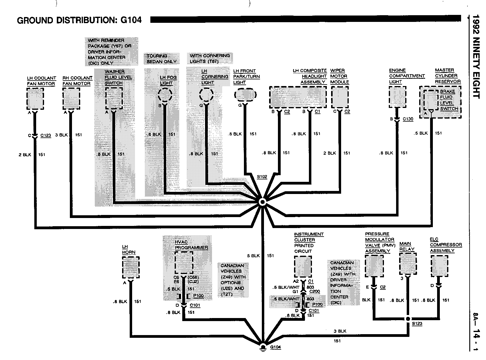
8A-10-1, Change the 3 RED (1 441) wire between terminal C of the Head/Park 8A-12-0, Light Switch and terminal G13 of in-line connector C200 to 5 RED (1441). 8A-101-0 8A-11-4 Change HVAC Programmer terminal C13 to C13 with C68 and to E13 with CJ2. 8A-11-7 Change HVAC Programmer terminal C12 to C12 with C68 and to E12 with CJ2. 8A-11-8, Change in-line connector C200 terminal B3, between splice S245 and 8A-61-0 the DIC Switch Assembly to B4. 8A-14-4, Change the 0.5 BLK (1 52) wire between terminal B of the Luggage 8A-135-0 Compartment Lid Latch Switch and splice S267 to 1 BLK (152). 8A-50-0 Change HVAC Programmer terminal C10 to C10 with C68 and E11 with CJ2. Change HVAC Programmer terminal C11 to C11 with C68 and E11 with CJ2. 8A-67-3 Change the condition "Measure voltage from HVAC Programmer connector, terminal C3, to ground" Located in the lower left corner of the page) to "Measure voltage from HVAC Programmer connector, terminal C3 with C68 or E3 with CJ2. 8A-67-4 Change the condition "Measure voltage from HVAC Programmer terminal D4 to ground located in the upper left corner) to "Measure voltage from HVAC Programmer terminal, D4 with C68 or F4 with CJ2. 8A-68-11, Change the color of the HVAC Programmer connector to BLU 8A-68-12 8A-68-35 Change D and C at the HVAC Programmer connector to F and E. Change the color of the HVAC Programmer to ORN. 8A-68-38 Change F and E at the HVAC Programmer connector to C and D. 8A-89-2 Change HVAC Programmer terminal C5 to C5 with C68 and to E5 with CJ2. Change HVAC Programmer terminal C7 to C7 with C68 and to E7 with CJ2. 8A-133-0 Change in-line connector C200 terminal J9, between the instrument Cluster and the Pass-Key Decoder Module to E13.
General Motors bulletins are intended for use by professional technicians, not a "do-it-yourselfer". They are written to inform those technicians of conditions that may occur on some vehicles, or to provide information that could assist in the proper service of a vehicle. Properly trained technicians have the equipment, tools, safety instructions and know-how to do a job properly and safely. If a condition is described, do not assume that the bulletin applies to your vehicle, or that your vehicle will have that condition. See a General Motors dealer servicing your brand of General Motors vehicle for information on whether your vehicle may benefit from the information.
