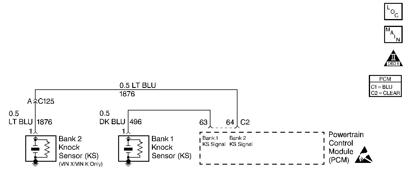
Circuit Description
The knock sensors are used to detect engine detonation, allowing the PCM to retard Ignition Control (IC) spark timing based on the KS signal being received. The knock sensors produce an AC signal which rides on a 5 volts DC signal supplied by the PCM. The signal amplitude and frequency is dependent upon the amount of knock being experienced.
The PCM determines whether the knock sensors and related wiring are operating properly by monitoring the voltage level on the noise channel. The noise channel allows the PCM to diagnose the KS system by allowing the PCM to learn the amount of normal engine mechanical noise present. Normal engine noise varies depending on engine speed and load. When the PCM determines that an abnormally low noise channel voltage level is being experienced, a DTC P0327 will set.
Conditions for Setting the DTC
| • | No active TP sensor, VSS, ECT, IC/Bypass Line Monitor, or CKP DTC(s) are set. |
| • | Engine has been running for at least 10 seconds. |
| • | Engine coolant temperature is greater than 65°C (149°F). |
| • | Throttle angle is greater than 1%. |
| • | Engine speed is between 2600 RPM and 2900 RPM. |
| • | System voltage is greater than 9 volts. |
| • | The PCM is monitoring a ESC noise channel voltage level below 0.5 volt. |
Action Taken When the DTC Sets
| • | The PCM will not illuminate the Malfunction Indicator Lamp (MIL). |
| • | The PCM will store conditions which were present when the DTC set as Fail Records data only. This information will not be stored as Freeze Frame data. |
| • | The PCM will use a calculated spark retard value to minimize knock during conditions when knock is likely to occur. The calculated value will vary based on engine speed and load. |
Action Taken When the DTC Sets
| • | The PCM will not illuminate the malfunction indicator lamp (MIL). |
| • | The PCM will store conditions which were present when the DTC set as Failure Records data only. This information will not be stored as Freeze Frame data. |
Diagnostic Aids
Check for the following conditions:
| • | Poor connection at PCM. Inspect knock sensor and PCM connectors for backed out terminals, broken locks, and improperly formed or damaged terminals. |
| • | Misrouted harness. Inspect the knock sensor harness to ensure that it is not routed too close to high voltage wires such as spark plug leads. |
Reviewing the Fail Records vehicle mileage since the diagnostic test last failed may help determine how often the condition that caused the DTC to be set occurs. This may assist in diagnosing the condition.
Test Description
Number(s) below refer to the step number(s) on the Diagnostic Chart.
-
Checks that the fault is present.
-
Checks that the knock sensor is capable of detecting detonation.
-
This vehicle is equipped with a PCM which utilizes an Electrically Erasable Programmable Read Only Memory (EEPROM). When the PCM is being replaced, the new PCM must be programmed. Refer to Powertrain Control Module Replacement/Programming .
Step | Action | Value(s) | Yes | No |
|---|---|---|---|---|
1 | Was the Powertrain On-Board Diagnostic System Check performed? | -- | ||
Note test result; does scan tool indicate DTC P0327 failed this ign? | -- | |||
3 |
Note test result; does scan tool indicate DTC P0327 failed this ign? | -- | Refer to Diagnostic Aids | |
4 |
Does DVM indicate voltage at the specified value? | 5V | ||
5 | Measure the resistance of the knock sensor by connecting the DVM between the knock sensor terminal and the engine block. Is resistance of the knock sensor near the specified value? | 100K ohms | ||
Is any signal indicated on the DVM while tapping on the engine lift bracket? | -- | |||
7 |
Was a problem found? | -- | ||
8 |
Was a problem found? | -- | ||
9 | Replace the knock sensor. Refer to Knock Sensor Replacement . Is action complete? | -- | -- | |
10 |
Was a problem found? | -- | ||
11 |
Was a problem found? | -- | ||
12 |
Note test result; does scan tool indicate DTC P0327 failed this ign? | -- | ||
Replace the PCM. Important: Replacement PCM must be programmed. Refer to Powertrain Control Module Replacement/Programming . Is action complete? | -- | -- | ||
14 |
Note test result; does scan tool indicate DTC P0327 failed this ign? | -- | System OK |
