SERVICE MANUAL UPDATE SEC. 10 UNDER BODY DIMENSION CHANGE

Subject: SERVICE MANUAL UPDATE - SECTION 10 BODY (UNDERBODY, ENGINE COMPARTMENT, FRONT DOOR AND HOOD HINGE DIMENSIONS CHANGE)
Models Affected: 1982 - 1991 'A' MODELS
1991 Pontiac 6000 Pages 10-3-2, 10-3-3, 10-3-7 and 10-3-8.
1991 Oldsmobile Cutlass Ciera and Cutlass Cruiser Oages 10-3-2, 10-3-3 and 10-3-8
1991 Buick Century Pages 10-3-2, 10-3-3, 10-3-7 and 10-3-8
1991 Chevrolet Celebrity and Pontiac 6000 Pages 10-3-2, 10-3-3, 10-3-4 and 10-3-5
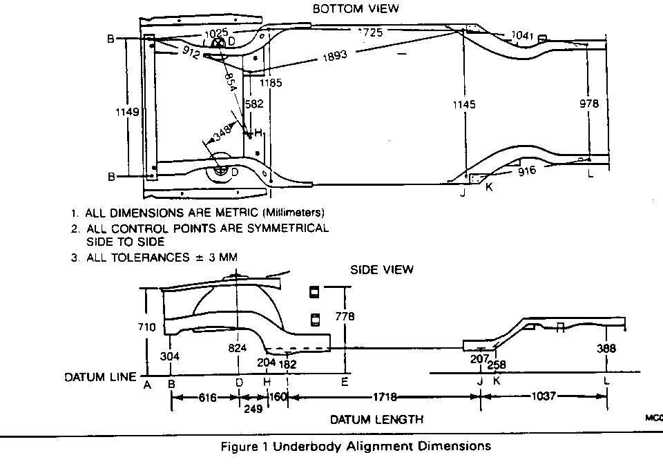
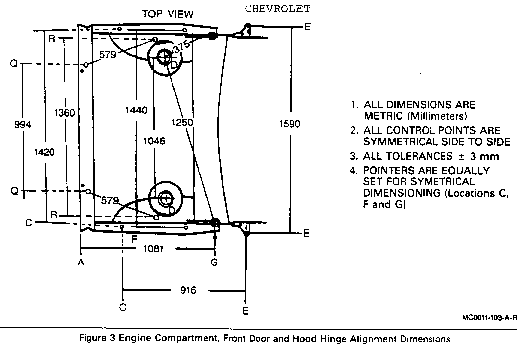
Due to a redesigned front fender wheelhouse panel, the body alignment dimensions and measurement locations at the strut towers have changed. Reference Point "D" has changed from the center of strut shock tower front attaching hole, to the center of the strut shock tower 90mm (3-9/16") hole.
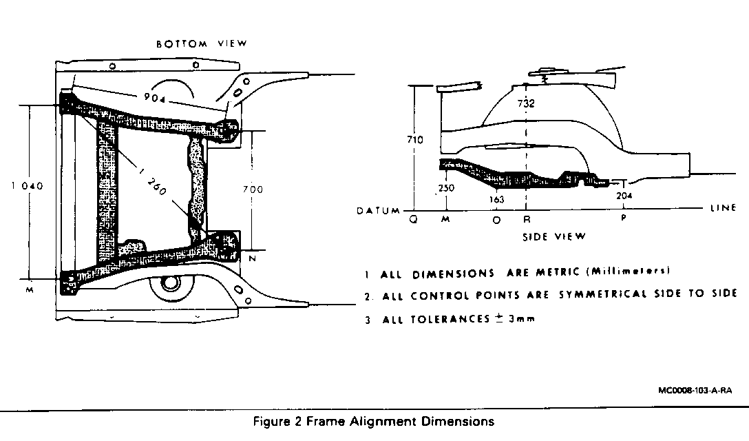
The following information replaces Figures 2, 3, 4, 7 and 8 in the 1991 Pontiac 6000 , Buick Century, and Oldsmobile Cutlass Ciera and Cutlass Cruiser Service Manuals, Section 10-3.
Section 10-3 with these revised dimensions should be used for all prior model year "A" cars replacing any information in prior manuals referring to the frame and underbody.
This information also replaces Figures 1, 2, 3, 4 and 5 in 1990 Chevrolet/Pontiac A-carline Service Manual, Section 10-3 and should be used in place of any information in prior Chevrolet Service Manuals referring to the underbody.
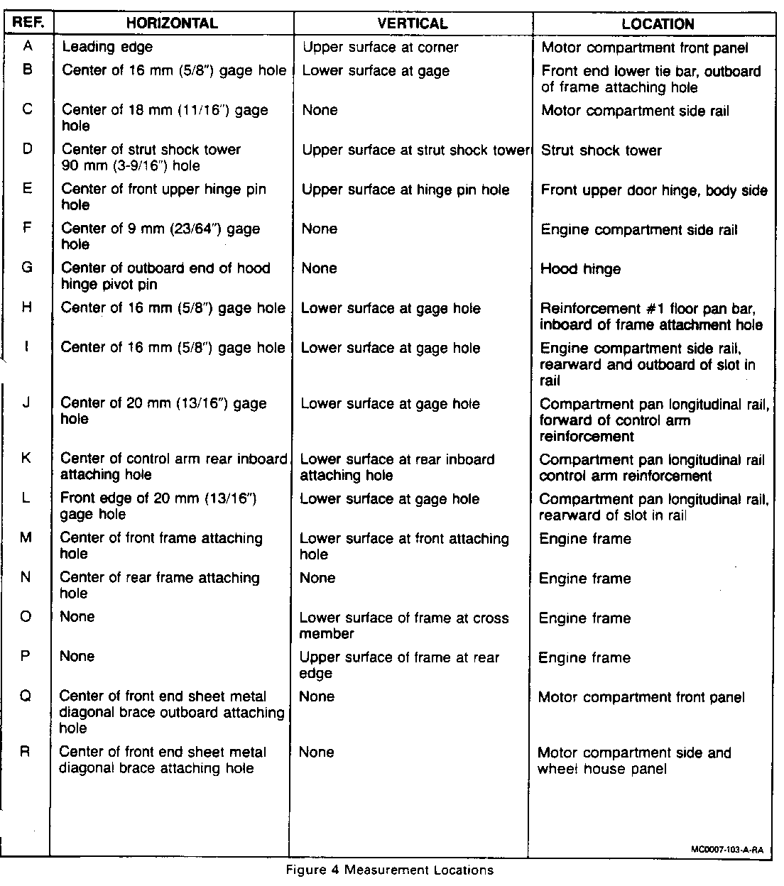
CHEVROLET REF. HORIZONTAL VERTICAL LOCATION --- ---------------- ---------------- ----------------- A Leading edge Upper surface at Motor compartment corner front panel,
B Center of 16mm (5/8") Lower surface at gage Front end lower tie gage hole bar, outboard of
C Center of 18 mm None Motor compartment (11/16") gage hole side rail
D Center of strut Upper surface at Strut shock tower shock tower 90mm strut shock tower (3-9/16") hole
E Center of front Upper surface at hinge Front upper door upper hinge pin pin hole hinge, body side hole
F Center of 9mm None Engine compartment (23/64") gage hole side rail
G Center of outboard None Hood hinge end of hood hinge pivot pin
H Center of 16mm Lower surface at Reinforcement #1 floor (5/8") gage hole gage hole pan bar, inboard of frame attachment hole
I Center of 16mm Lower surface at Engine compartment (5/8") gage hole gage hole side rail, rearward and outboard of slot in rail
J Center of 20mm Lower surface at Compartment pan (13/16") gage hole gage hole longitudinal rail, forward of control arm reinforcement
K Center of control Lower surface at Compartment pan arm rear inboard rear inboard longitudinal rail attaching hole attaching hole control arm reinforcement
L Front edge of Lower surface at Compartment pan 20mm (13/16") gage hole longitudinal rail, gage hole rearward of slot in rail
M Center of front Lower surface at Engine frame frame attaching front attaching hole hole
N Center of rear frame None Engine frame attaching hole
0 None Lower surface of Engine frame frame at cross member
P None Upper surface of Engine frame frame at rear edge
Q Center of front None Motor compartment end sheet metal front panel diagonal brace outboard attaching hole
R Center of front None Motor compartment end sheet metal side and diagonal brace wheel house panel attaching hole
Figure 4 Measurement Locations CHEVROLET
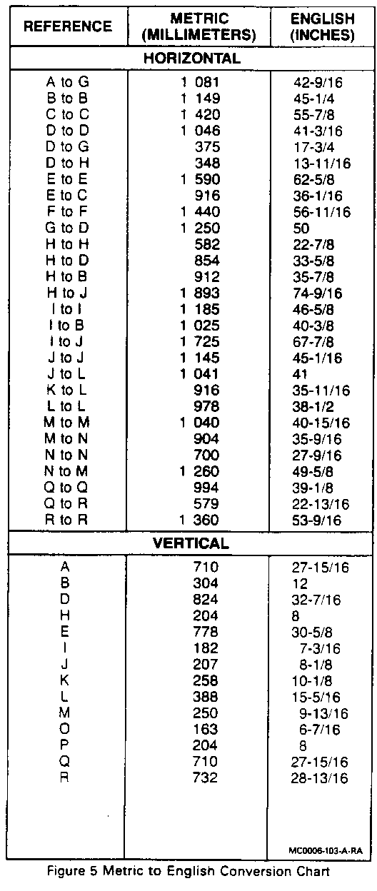
METRIC ENGLISH REFERENCE (MILLIMETERS) (INCHES) ---------- ------------- -------- H O R I Z O N T A L ******************************************************** A - G 1 081 42-9/16 B - B 1 149 45-1/4 C - C 1 420 55-7/8 D - D 1 046 41-3/16 D - G 375 17-3/4 D - H 348 13-11/16 E - E 1 590 62-5/8 E - C 916 36-1/16 F - F 1 440 56-11/16 G - D 1 250 50 H - H 582 22-7/8 H - D 584 33-5/8 H - B 912 35-7/8 H - J 1 893 74-9/16 I - I 1 185 46-5/8 I - B 1 025 40-3/8 I - J 1 725 67-7/8 J - J 1 145 45-1/16 J - L 1 041 41 K - L 916 35-11/16 L - L 978 38-1/2 M - M 1 040 40-15/16 M - N 904 35-9/16 N - N 700 27-9/16 N - M 1 260 49-5/8 Q - Q 994 39-1/8 Q - R 579 22-13/16 R - R 1 360 53-9/16
V E R I C A L ******************************************************** A 710 27-15/16 B 304 12 D 824 32-7/16 H 204 8 E 778 30-5/8 I 182 7-3/16 J 207 8-1/8 K 258 10-1/8 L 388 15-5/16 M 250 9-13/16 O 163 6-7/16 P 204 8 Q 710 27-15/16 R 732 28-13/16
PONTIAC-OLDSMOBILE-BUICK REF. HORIZONTAL VERTICAL LOCATION --- ---------------- ---------------- ----------------- A Leading edge Upper surface at Motor compartment corner front panel,
B Center of 16mm (5/8") Lower surface at gage Front end lower tie gage hole bar, outboard of
C Center of 18 mm None Motor compartment (11/16") gage hole side rail
D Center of strut Upper surface at Strut shock tower shock tower 90mm strut shock tower (3-9/16") hole
E Center of front Upper surface at hinge Front upper door upper hinge pin pin hole hinge, body side hole
F Center of 9mm None Engine compartment (23/64") gage hole side rail
G Center of outboard None Hood hinge end of hood hinge pivot pin
H Center of 16mm Lower surface at Reinforcement #1floor (5/8") gage hole gage hole pan bar, inboard of frame attachment hole
I Center of 16mm Lower surface at Engine compartment (5/8") gage hole gage hole side rail, rearward and outboard of slot in rail
J Center of 20mm Lower surface at Compartment pan (13/16") gage hole gage hole longitudinal rail, forward of control arm reinforcement
K Center of control Lower surface at Compartment pan arm rear inboard rear inboard longitudinal rail attaching hole attaching hole control arm reinforcement
L Front edge of Lower surface at Compartment pan 20mm (13/16") gage hole longitudinal rail, gage hole rearward of slot in rail
M Center of front Lower surface at Engine frame frame attaching front attaching hole hole
N Center of rear frame None Engine frame attaching hole
0 None Lower surface of Engine frame frame at cross member
P None Upper surface of Engine frame frame at rear edge
Q Center of front None Motor compartment end sheet metal front panel diagonal brace outboard attaching hole
R Center of front None Motor compartment end sheet metal side and diagonal brace wheel house panel attaching hole
Figure 4 Measurement Locations
PONTIAC-OLDSMOBILE-BUICK METRIC ENGLISH REFERENCE (MILLIMETERS) (INCHES) ---------- ------------- -------- H O R I Z O N T A L ******************************************************** A - G 1 081 42-9/16 B - B 1 149 45-1/4 C - C 1 420 55-7/8 D - D 1 046 41-3/16 D - G 375 17-3/4 D - H 348 13-11/16 E - E 1 590 62-5/8 E - C 916 36-1/16 F - F 1 440 56-11/16 G - D 1 250 50 H - H 582 22-7/8 H - D 584 33-5/8 H - B 912 35-7/8 H - J 1 893 74-9/16 I - I 1 185 46-5/8 I - B 1 025 40-3/8 I - J 1 725 67-7/8 J - J 1 145 45-1/16 J - L 1 041 41 K - L 916 35-11/16 L - L 978 38-1/2 M - M 1 040 40-15/16 M - N 904 35-9/16 N - N 700 27-9/16 N - M 1 260 49-5/8 Q - Q 994 39-1/8 Q - R 579 22-13/16 R - R 1 360 53-9/16
V E R I C A L ******************************************************** A 710 27-15/16 B 304 12 D 824 32-7/16 H 204 8 E 778 30-5/8 I 182 7-3/16 J 207 8-1/8 K 258 10-1/8 L 388 15-5/16 M 250 9-13/16 O 163 6-7/16 P 204 8 Q 710 27-15/16 R 732 28-13/16
General Motors bulletins are intended for use by professional technicians, not a "do-it-yourselfer". They are written to inform those technicians of conditions that may occur on some vehicles, or to provide information that could assist in the proper service of a vehicle. Properly trained technicians have the equipment, tools, safety instructions and know-how to do a job properly and safely. If a condition is described, do not assume that the bulletin applies to your vehicle, or that your vehicle will have that condition. See a General Motors dealer servicing your brand of General Motors vehicle for information on whether your vehicle may benefit from the information.
