For 1990-2009 cars only
Removal Procedure
- Disconnect the negative battery cable.
- Install the J 28467-360 . Refer to Engine Support Fixture .
- Remove the front transmission mount bolts. Refer to Transmission Front Mount Replacement
- Remove the splash shield. Refer to Wheelhouse Splash Shield Replacement in Body Front End.
- Remove the air cleaner and duct assembly from the throttle body. Refer to Air Cleaner Assembly Replacement in Engine Controls - 2.4L or Air Cleaner Assembly Replacement in Engine Controls - 3.1L.
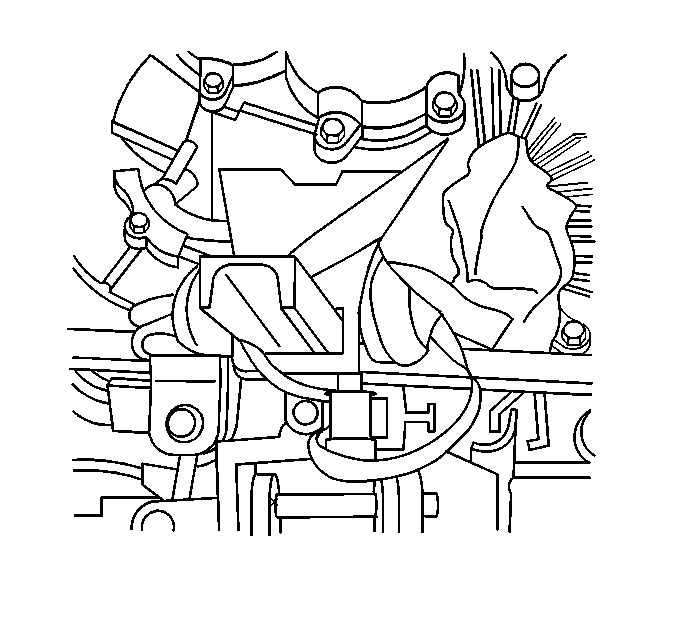
- Remove the wire harness from the upper transaxle mount bracket.
- Remove the side transaxle mount. Refer to Transmission Mount Replacement - Side .
- Remove the shifter cable. Refer to Transmission Control Replacement .
- Secure the vehicle radiator and condenser to the upper radiator support.
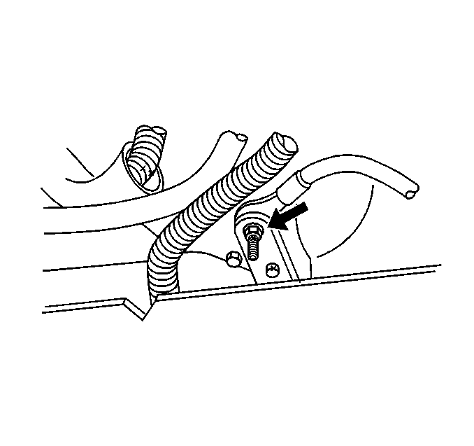
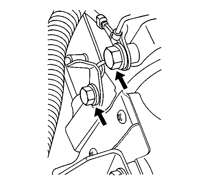
- Remove the ground cables from the engine block.
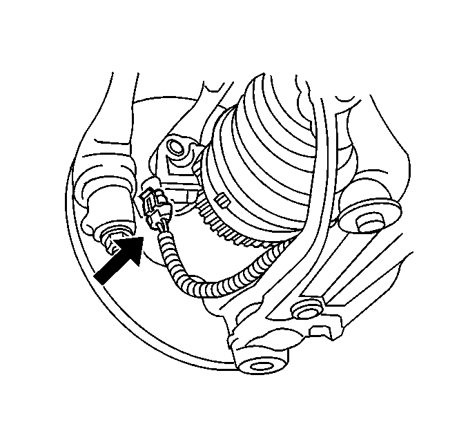
- Disconnect the park neutral position (PNP) switch connector.
- Raise and support the vehicle. Refer to Lifting and Jacking the Vehicle in General Information.
- Support the vehicle with a safety stand.
- Drain the transaxle. Refer to Oil Pan Replacement .
- Remove the front tire and wheel assemblies. Refer to Tire and Wheel Removal and Installation in Tires and Wheels.
- Remove the left and right front inner splash shields. Refer to Wheelhouse Splash Shield Replacement in Body Front End.
- Remove the lower radiator and condenser support. Refer to Radiator Lower Mounting Panel Replacement in Body Front End.
- Remove the front transmission mount bracket bolts and bracket. Refer to Radiator Lower Mounting Panel Replacement .
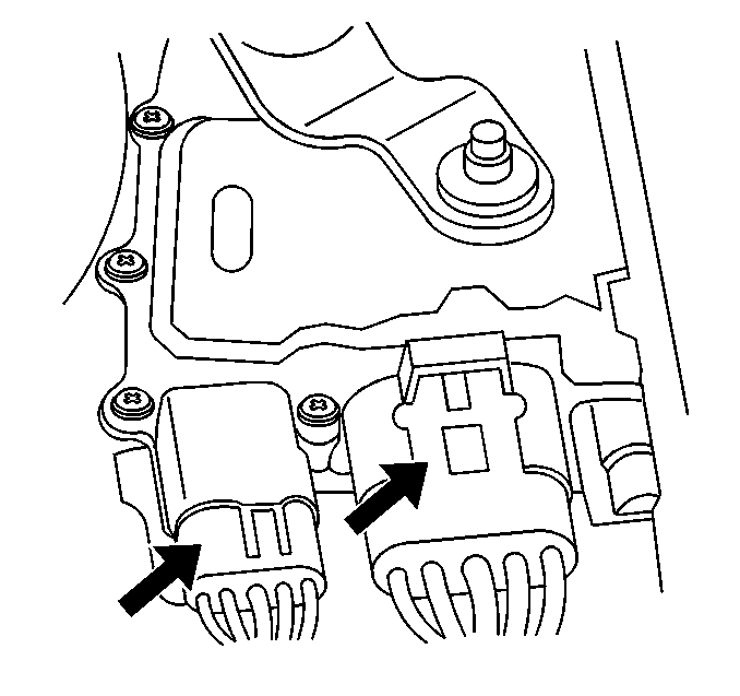
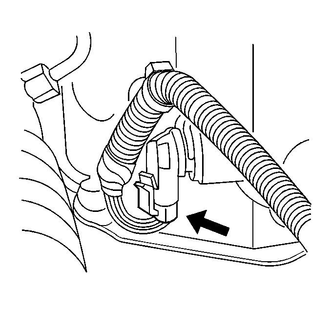
- Remove the front Antilock Brake System (ABS) Wheel Speed Sensor (WSS) connectors.
- Unroute the ABS WSS harness.
- Remove the brake modulator assembly bolts and the brake modulator assembly. Refer to Brake Pressure Modulator Valve Assembly Replacement in Antilock Brake System.
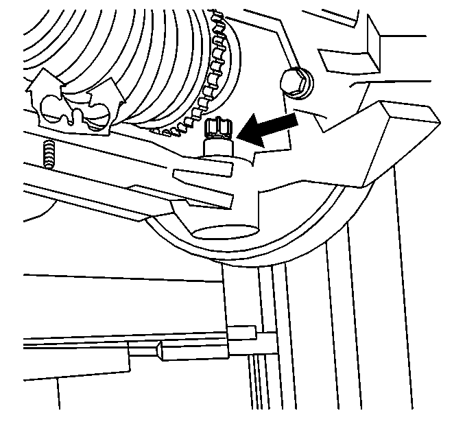
- Remove the vehicle speed sensor.
- Remove the torque converter bolts. Refer to Flywheel to Torque Converter Bolt Replacement .
- Remove the left and right ball joint nuts.
- Unroute the ABS WSS harness.
- Separate the ball joint from the control arm. Refer to Lower Control Arm Ball Joint Replacement in Front Suspension.
- Remove the drive axles. Refer to Wheel Drive Shaft Replacement in Wheel Drive Shafts.
- Remove the front transaxle mount. Refer to Transmission Front Mount Replacement .
- Remove the ABS module. Refer to Brake Pressure Modulator Valve Assembly Replacement in Antilock Brake System.
- Separate the tie rod ends from the steering knuckles. Refer to Rack and Pinion Outer Tie Rod End Replacement in Power Steering System.
- Disconnect the power steering pressure line from the rack and pinion. Refer to Steering Linkage Inner Tie Rod Replacement in Power Steering System.
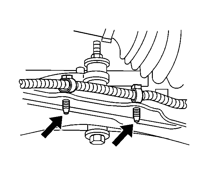
- Remove the brake lines from the retainer below the rack and pinion.
- Remove the steering column pinch bolt and position the intermediate shaft aside. Refer to Intermediate Steering Shaft Replacement in Power Steering System.
- Attach the transaxle case to the support stand.
- Remove the transaxle-to-engine mount bolts.
- Remove the transaxle:
- Flush the transmission cooler and lines. Refer to Transmission Fluid Cooler Flushing and Flow Test .
Caution: Unless directed otherwise, the ignition and start switch must be in the OFF or LOCK position, and all electrical loads must be OFF before servicing any electrical component. Disconnect the negative battery cable to prevent an electrical spark should a tool or equipment come in contact with an exposed electrical terminal. Failure to follow these precautions may result in personal injury and/or damage to the vehicle or its components.
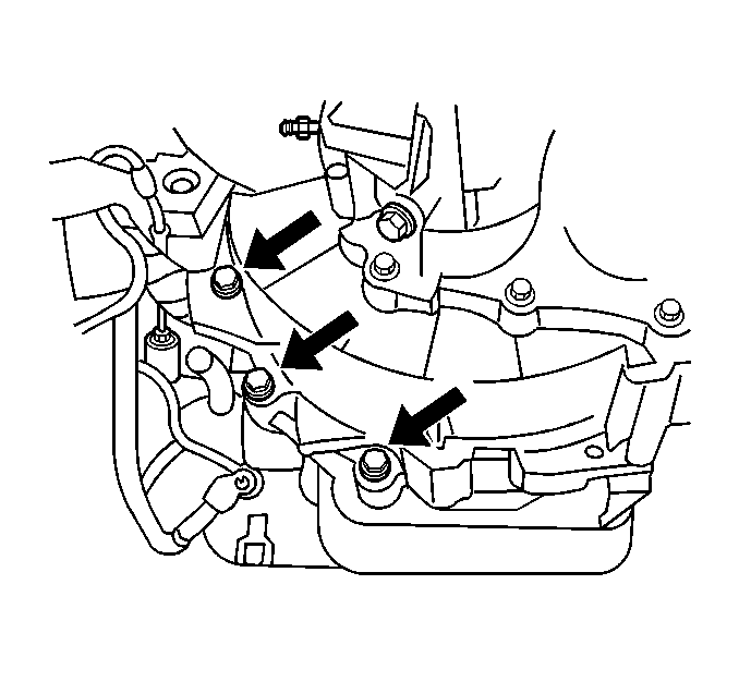
| 36.1. | Slide the transaxle away from the engine. |
| 36.2. | Carefully lower the support stand. |
Installation Procedure
- Install the transaxle:
- Install the transaxle-to-engine mount bolts.
- Detach the transaxle case from the support stand.
- Install the steering column pinch bolt and position the intermediate shaft. Refer to Intermediate Steering Shaft Replacement in Power Steering System.
- Install the brake lines to the retainer below the rack and pinion.
- Connect the power steering pressure line to the rack and pinion. Refer to Power Steering Pressure Pipe/Hose Replacement in Power Steering System.
- Install the tie rod ends to the steering knuckles. Refer to Rack and Pinion Outer Tie Rod End Replacement in Power Steering System.
- Install the ABS module. Refer to Brake Pressure Modulator Valve Assembly Replacement in Antilock Brake System.
- Install the front transaxle mount. Refer to Transmission Front Mount Replacement .
- Install the drive axles. Refer to Wheel Drive Shaft Replacement in Wheel Drive Shafts.
- Install the ball joint to the control arm. Refer to Lower Control Arm Ball Joint Replacement in Front Suspension.
- Install the left and right ball joint nuts.
- Install the torque converter bolts. Refer to Flywheel to Torque Converter Bolt Replacement .
- Install the vehicle speed sensor.
- Install the brake modulator assembly bolts and the brake modulator assembly. Refer to Brake Pressure Modulator Valve Assembly Replacement in Antilock Brake System.
- Install the front Antilock Brake System (ABS) Wheel Speed Sensor (WSS) connectors.
- Install the front transmission mount bracket bolts and bracket. Refer to Transmission Front Mount Replacement .
- Install the lower radiator and condenser support. Refer to Radiator Lower Mounting Panel Replacement in Body Front End.
- Install the left and right front inner splash shields. Refer to Wheelhouse Splash Shield Replacement in Body Front End.
- Install the front tire and wheel assemblies. Refer to Tire and Wheel Removal and Installation in Tires and Wheels.
- Fill the transaxle. Refer to Oil Pan Replacement .
- Support the vehicle with a safety stand.
- Lower the vehicle.
- Connect the PNP switch connector.
- Install the ground cables from the engine block.
- Secure the vehicle radiator and condenser to the upper radiator support. Refer to Radiator Lower Mounting Panel Replacement in Engine Cooling.
- Install the shifter cable. Refer to Transmission Control Replacement .
- Install the upper transaxle mount. Refer to Transmission Front Mount Replacement .
- Install the wire harness from the upper transaxle mount bracket.
- Install the air cleaner and duct assembly to the throttle body. Refer to Air Cleaner Assembly Replacement in Engine Controls - 2.4L or Air Cleaner Assembly Replacement in Engine Controls - 3.1L.
- Install the splash shield. Refer to Wheelhouse Splash Shield Replacement in Body Front End.
- Install the front transmission mount bolts. Refer to Transmission Front Mount Replacement .
- Remove the J 28467-360 . Refer to Engine Support Fixture .
- Connect the negative battery cable.
| 1.1. | Slide the transaxle towards the engine. |
| 1.2. | Carefully raise the support stand. |
