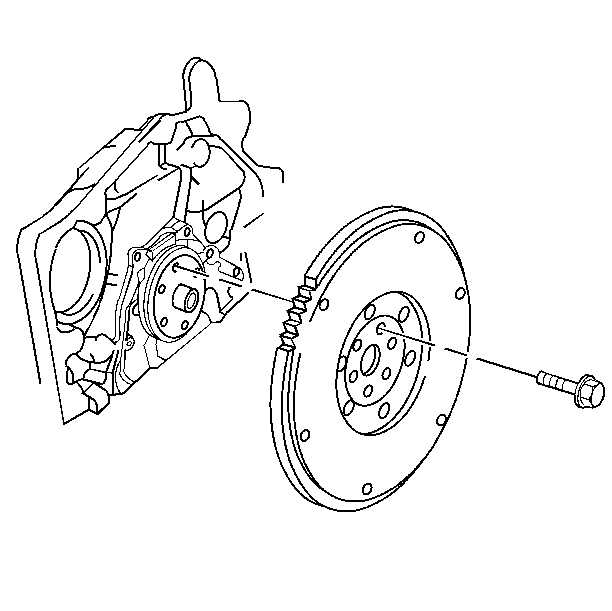
Removal Procedure
Tools Required
Important: You may be required to remove the chamfer from the edge of an 18-mm
socket in order to obtain a full socket engagement on the thin headed flywheel
bolts.
You cannot balance the flywheel to the engine by rotating the flywheel,
because the flywheel can only be installed on the crankshaft one way.
- Remove the transmission assembly. Refer to
Transmission Replacement
in Automatic Transaxle - 4T40 - E/4T45 -
E.
- Remove the right splash shield. Refer to
Wheelhouse Splash Shield Replacement
in Body
Front End.
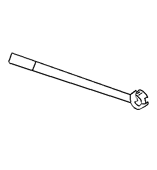
- Remove the flywheel attaching bolt while using J 38122-A
. This will prevent crankshaft rotation.
- Remove the flywheel and retainer.
- Thoroughly remove the thread adhesive from the following locations:
| • | The crankshaft threaded holes |
Installation Procedure
- Install new bolts or apply adhesive/sealant compound GM P/N 123454493
or equivalent to the bolts which you are reusing.
- Carefully follow the instructions included with the thread locking
compound in order to ensure proper bolt retention.
- Install the flywheel and
the attaching bolts.
- While holding the crankshaft balancer with J 38122-A
, tighten the bolts evenly to 30 N·m
(22 lb ft), + 45 degrees using J 36660-A
.
- Install the right splash shield. Refer to
Wheelhouse Splash Shield Replacement
in Body
Front End.
- Install the transmission assembly. Refer to
Transmission Replacement
in Automatic Transaxle
4T40 - E/4T45 - E.
