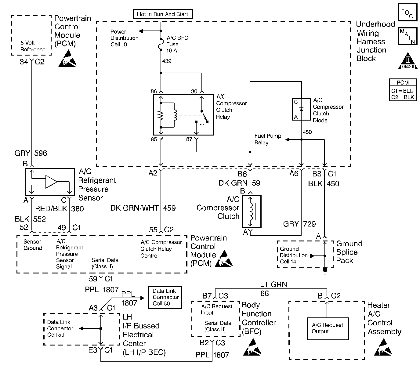
Circuit Description
The air conditioning (A/C) refrigerant pressure sensor responds to the changes in the A/C refrigerant high side pressure. This input indicates how much load the A/C compressor is putting on the engine, and is one of the factors used by the Powertrain Control Module (PCM) in order to determine the idle air control (IAC) position for the idle speed. The circuits consist of a 5 volt reference and a ground, both provided by the PCM, and a signal from the sensor. The signal is a voltage which is proportional to the A/C pressure. The sensor's operating range is between 0 and 459 psi. At 0 psi, the signal voltage will be about 0.1 volt, varying to about 4.9 volt at 459 psi.
Conditions For Setting The DTC
The A/C refrigerant sensor pressure is greater than 453 psi (4.90 V) with the A/C requested.
OR
The A/C refrigerant sensor pressure is greater than 363 psi (4.0 V) with the A/C not requested
OR
The A/C refrigerant pressure sensor is less than 0 psi (0.10V) when the intake air temperature is greater than 0°C (32°F) and DTC P0112 or P0113 is not set.
The A/C refrigerant sensor pressure is less than 0 psi (0.10 V) when an IAT sensor DTC is present.
Any of the above conditions are met for 15 seconds.
Action Taken When the DTC Sets
| • | The PCM will record the operating conditions at the time during which the diagnostic fails. This information will store in the Failure Records buffer. |
| • | A history DTC stores. |
| • | The PCM will disable the A/C compressor clutch. |
Conditions for Clearing the MIL/DTC
| • | A history DTC will clear after 40 consecutive warm up cycles without a fault. |
| • | A scan tool can clear the MIL/DTCs. |
Diagnostic Aids
| • | The DTC P0530 sets when the signal voltage falls outside of the normal possible range of the sensor. |
| • | If the actual pressure of the A/C system matches the scan tool readings, repair any A/C pressure problems before using this table. Refer to the Air Conditioning System section of the service manual. |
| • | Thoroughly check any suspected circuitry for the following conditions: |
| - | Backed out terminals |
| - | Improper mating of the terminals |
| - | Broken locks |
| - | Improperly formed or damaged terminals |
| - | Poor terminal to wiring connections |
| - | Physical damage to the wiring harness |
Test Description
The number(s) below refer(s) to the step number(s) on the Diagnostic Table.
-
The Powertrain OBD System Check prompts you to complete some of the basic checks and to store the freeze frame and failure records data on the scan tool if applicable. This creates an electronic copy of the data captured when the malfunction occurred. The scan tool stores this data for later reference.
-
If the MAP or TP sensor DTC is set, this indicates that the malfunctioning circuit is diagnosed in those tables. Refer to the appropriate table.
-
Reprogram the replacement PCM and perform the crankshaft position system variation learn procedure. Refer to the latest Techline information for PCM programming and Crankshaft Position System Variation Learn for the crankshaft position system variation learn procedure.
-
If no malfunctions are present at this point and no additional DTCs were set, refer to the Diagnostic Aids for additional checks and information.
Step | Action | Value(s) | Yes | No | ||||
|---|---|---|---|---|---|---|---|---|
Did you perform the Powertrain On-Board Diagnostic (OBD) System Check? | -- | |||||||
Were any MAP or TP DTCs also set? | -- | Go to MAP or TP DTC Tables | ||||||
3 | Does the A/C high side value read greater than the specified value? | 3.0 V (279 psi) | ||||||
4 |
Does the DMM measure the specified voltage? | B+ | ||||||
5 |
Is the voltage greater than the specified value? | 0.5 V | ||||||
6 |
Was a repair necessary? | -- | ||||||
7 |
Was a repair necessary? | -- | ||||||
8 | Replace the A/C refrigerant pressure sensor. Refer to Air Conditioning (A/C) Refrigerant Pressure Sensor Replacement in HVAC Systems with AC-Manual. Is the action complete? | -- | -- | |||||
Replace the PCM. Refer to the Powertrain Control Module Replacement/Programming . Is the action complete? | -- | -- | ||||||
10 |
Does the scan tool indicate that this diagnostic has ran and passed? | -- | ||||||
Check to see if any additional DTCs are set. Does the scan tool display any DTCs that you have not diagnosed? | -- | Go to applicable DTC table | System OK |
