POWER MASTER SERVICE KITS REPAIR KIT PART NUMBERS

VEHICLES AFFECTED: 1986 B-WAGONS, 1985-87 BUICK "G" TURBO CARS
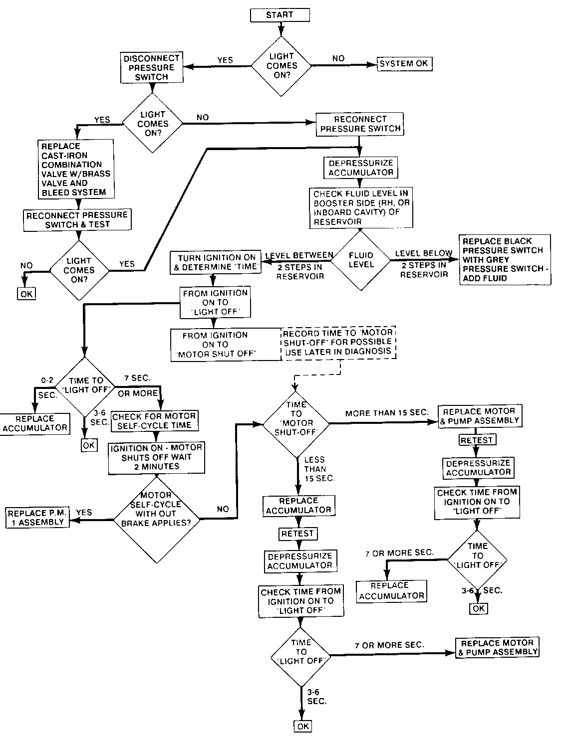
This bulletin has been revised to add a diagnostic flow chart. This chart should help in understanding the logic behind the diagnostic procedures described in the bulletin.
This bulletin provides brake diagnostic information that will help to correctly diagnose and resolve concerns with the Powermaster brake system on 1986 B Station Wagons and Buick 1985-87 Regal Turbo vehicles.
CONDITION: Owners of some 1986 "B" wagons or 1985-87 Regal Turbo vehicles equipped with the Powermaster Brake System may experience either "Harder Pedal Feel" or "Increased Pedal Travel". CAUSE:
A. "Harder Pedal Feel" symptoms can be diagnosed from this bulletin, but specific initial attention should be placed on two areas as a likely cause for this and can be repaired with a component kit.
1. Booster pressure switch - leaking fluid externally.
2. Accumulator - low gas charge.
B. "Increased Pedal Travel" symptoms can be diagnosed from this bulletin but are likely to be caused by air ingestion into the cast iron combination brake valve, requiring a new brass replacement valve.
1. Brake combination valve - air ingestion into the left front brake pipe. No external fluid leak occurs.
NOTE: Replacement of the complete Powermaster assembly is not required to correct most customer concerns. Part kits are available that will resolve most concerns with this system, and eliminate unnecessary replacement of the complete Powermaster assembly.
*CORRECTION: HARD PEDAL
Diagnostics Result Corrective Action
Check fluid level on Below minimum See Step 1 booster side "after" gauge mark 10 brake applies with ignition off. Check reservoir on the side away from pressure switch. Within normal level None required gauge marks
WARNING
Light Operation - With normal braking Light does not None required come on
- With normal braking Light comes on, See accumulator goes off operation
- With normal braking Light comes on, See booster may stay on motor operation or see Increased Pedal Travel Diagnostic
- If abnormally rapid Light may come on None required - brake applies made at and go off this is normal one apply per second operation
Accumulator Operation 0-2 seconds Replace (Test after 10 brake (accumulator accumulator - applies with ignition diaphragm is (after 10 brake off to depressurize leaking applies with accumulator: Then turn internally) ignition off) ignition on and check the time from motor "start" to light off 3-6 seconds None required (normal)
7 seconds or more See step 2
Booster Motor Operation Motor doesn't run, See step 3 Turn ignition on and no power assist, and make brake applies warning light is on
Motor doesn't shut off See step 4
INCREASED PEDAL TRAVEL
Diagnostics Result Corrective Action
Inspect for external Leakage observed Repair leak or leak replace leaking part. Add fluid to reservoir - outboard side
Test for Combination Pedal Travel* Replace valve air inqestion improves left combination Bleed left front front bleed valve with brass caliper only. valve #25509419 and rebleed total system
Pedal Travel * Rebleed total is still high system
*To properly evaluate pedal travel, apply brakes with vehicle parked, ignition off, and without power assist (depressurize accumulator with 10 brake applies). Pedal travel on the '86 B station wagon should be a maximum of 57mm (2 1/4") with normally worn brake linings when checked at 100# pedal force with J-28662 tool.
Step #1 - Low fluid in booster side (external leak)
A. Inspect the pressure switch and adjacent areas for external leak. This may require wiping those areas dry and observing during and after motor run.
NOTE: The pressure switch is the most likely cause of external leak, but can also dampen other areas such as the cowl or rear booster areas that will then appear to be leaking.
B. Depressurize system with 10 brake applies with ignition off before replacing pressure switch of other leaking part. Recheck fluid level on booster side, and add brake fluid to adjust level to within gauge marks in reservoir.
Step #2 - After Accumulator Operation Test indicates 7 seconds or more
A. Depressurize system with 10 brake applies with ignition off. Fluid level must be within gauge marks in reservoir.
B. Turn ignition on and wait until motor shuts off.
1. If motor does not self cycle in 2 minutes without brake apply, proceed to (C).
2. If motor does self cycle, an internal booster leak requires replacing the Powermaster assembly.
C. Install J35126 Tool and test to determine if fault is in motor and pump assembly, or in the accumulator.
1. Remove pressure switch.
2. Install J35126 into switch port.
3. Reinstall pressure switch into J35126.
4. Reconnect electrical connector.
D. Turn ignition on. Wait until motor shuts off. Turn ignition off. Slowly bleed off accumulator pressure with J35126 bleed valve returning fluid to booster side of reservoir. The gauge pressure will suddenly drop to zero at the accumulator gas pre-charge point.
1. If the drop off occurs below 1380 kPa (200 psi), replace the accumulator.
2. If the drop off occurs above 1380 kPa (200 psi), replace the pump and motor assembly.
E. NOTE: J35126 Tool per (2C) is the best method; however, if it is not available, an alternate method will help to determine fault between the pump and motor assembly and the accumulator.
1. Depressurize system per (2A). Turn ignition on, and check the time from motor start to motor "shut-off".
2. If time to motor shut-off is more than 15 seconds, replace motor and pump assembly, and then retest accumulator per Accumulator Operation Test. If time on that test again is 7 seconds or more, also replace the accumulator.
3. If time to motor shut-off is less than 15 seconds, replace accumulator, and then retest motor and pump assembly per Accumulator Operation Test. If time is 7 seconds or more, also replace motor and pump assembly.
Step #3- Booster Motor Doesn't Run
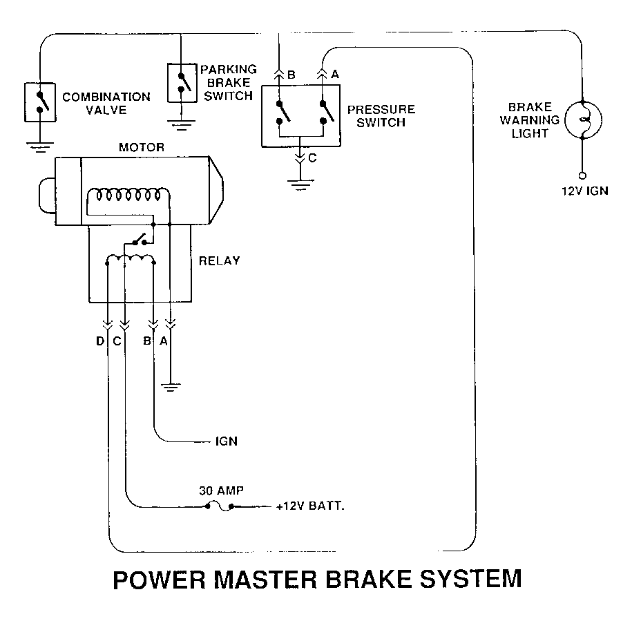
Confirm that 30 amp fuse is OK or replace. Then conduct electrical circuit checks. Disconnect the pressure switch and motor electrical connectors and test to the following:
A. Pressure Switch (Ohmmeter)
1. All switch terminals should have continuity with each other If not, replace switch.
B. Booster Motor (Ohmmeter)
1. Meter should show resistance between motor "B" and "D".
2. Meter should show open circuit between motor "A" and "C".
3. Replace motor and pump assembly if above are not met.
C. Pressure Switch Connector and Harness (Volt-Ohmmeter)
1. With ignition on, switch connector terminal "A" continuous with motor connector "D". (ohmmeter)
2. With ignition on, switch connector terminal "B" should be 12 volts to ground. (volt meter)
3. If "A" and "D" are not continuous, but "B" shows 12 volts, release parking brake.
4. Disconnect combination valve electrical connector.
D. Pump Connector and Harnes
1. Connector Terminal "A" continuous with chassis.
2. Connector Terminal "B" 12 volts to ground with ignition on.
3. Terminal "C" 12 volts to ground. This is the main electrical supply to the motor and is fused. If voltage does not appear at this terminal, check 30 amp fuse.
4. Terminal "D" previously checked in Step 3C1.
Step #4 - Motor doesn't shut off with ignition on
A. Check fluid level per Step 2A.
B. Install J35126 Tool per Step 2C and test to determine if fault is in motor and pump assembly, pressure switch, or internal booster leakage.
C. Monitor booster pressure on J35126 gauge. After 20 seconds with ignition on and without braking.
1. Pressure exceeds 5310 kPa (770 psi) replace pressure switch.
2. Pressure does not reach the 3725-5310 kPa (540-770 psi) pump shut-off range - check the front and rear holes in the bottom of the reservoir on booster side only.
A. If fluid is flowing into the reservoir through either hole, the booster is leaking internally and the complete powermaster assembly should be replaced.
B. If fluid is not flowing into the reservoir through either hole, the pump is unable to provide 3725-5310 kPa (540-770 psi) and the motor/pump assembly should be replaced.
Reference:
1. Parts:
The following repair kits have been released to assist in servicing the Powermaster brake units.
P/N Description
18011279 Pump and Motor Assembly Pkg. 18014977 Pressure Switch Assembly Pkg. 18014978 Accumulator Assembly Pkg. 18013293 Reservoir Cover Assembly Pkg. 18011398 Boot Pkg. 18010875 Bracket Pkg. 18011403 Sump Hose Pkg. 25509419 Brass Combination Valve
Parts are currently available from CANSPO.
2. Pump Pressure Ranges:
Pump Off 3725-5310 kPa (540-770 psi) Pump On 3380-3655 kPa (490-530 psi) Light On 2450-3000 kPa (355-435 psi)
A problem may be encountered in bleeding the Powermaster if for any reason the pump has not been properly filled with brake fluid. If after any service or new installation the pump does not circulate fluid after the motor has run for 20 seconds, it may be necessary to reprime the pump. In order to reprime the system, the following steps should be followed.
1. Turn off the ignition.
2. Apply the brake pedal with medium pressure 10-15 times with ignition off to discharge pressure from the accumulator.
3. Clean and remove reservoir cover.
4. Disconnect the booster tube and nut assembly from the casting boss at pump outlet. Refer to illustration.
5. Wait for brake fluid to gravity bleed from the disconnected end of the tubing.
6. When brake fluid begins to flow, reconnect the tube and torque to 17 N.m (13 ft. lbs.).
7. Check the fluid level in the reservoir and add new brake fluid if needed. Reinstall the reservoir cover.
8. Turn on the ignition. The pump should properly circulate the fluid to the fluid to the accumulator. The fluid level on the inboard side of the reservoir should diminish if the pump is working properly.
9. Continue with service manual bleed and fill procedure.


General Motors bulletins are intended for use by professional technicians, not a "do-it-yourselfer". They are written to inform those technicians of conditions that may occur on some vehicles, or to provide information that could assist in the proper service of a vehicle. Properly trained technicians have the equipment, tools, safety instructions and know-how to do a job properly and safely. If a condition is described, do not assume that the bulletin applies to your vehicle, or that your vehicle will have that condition. See a General Motors dealer servicing your brand of General Motors vehicle for information on whether your vehicle may benefit from the information.
