The New Venture Gear model NVG 126 RPO NP4 transfer case is a one speed automatic, active, transfer case. The NVG 126 provides only one mode, Auto 4WD, and is transparent to the operator. The active transfer case provides the benefits of on-demand torque biasing, wet clutch and easy vehicle tuning through software calibrations. The software calibrations allow more features, such as flexible adapt ready position and clutch pre-load torque levels. The technology allows for vehicle speed dependent clutch torque levels to enhance the performance of the system. For example, the system is calibrated to provide 0-7 N·m (0-62 lb in) of clutch torque during low speed, low engine torque operation, and predetermined higher torque for 32 km/h (20 mph) and greater. This prevents crow-hop and binding at low speeds, and provides higher torque biases at higher vehicle speeds, to enhance stability.
The NVG 126 requires no clutch shimming. The transfer case control module controls the clutch wear and clutch torque levels. The software learns adapt ready positions which are for the correct clutch torque. The learned adapt ready positions vary as the unit wears over its life.
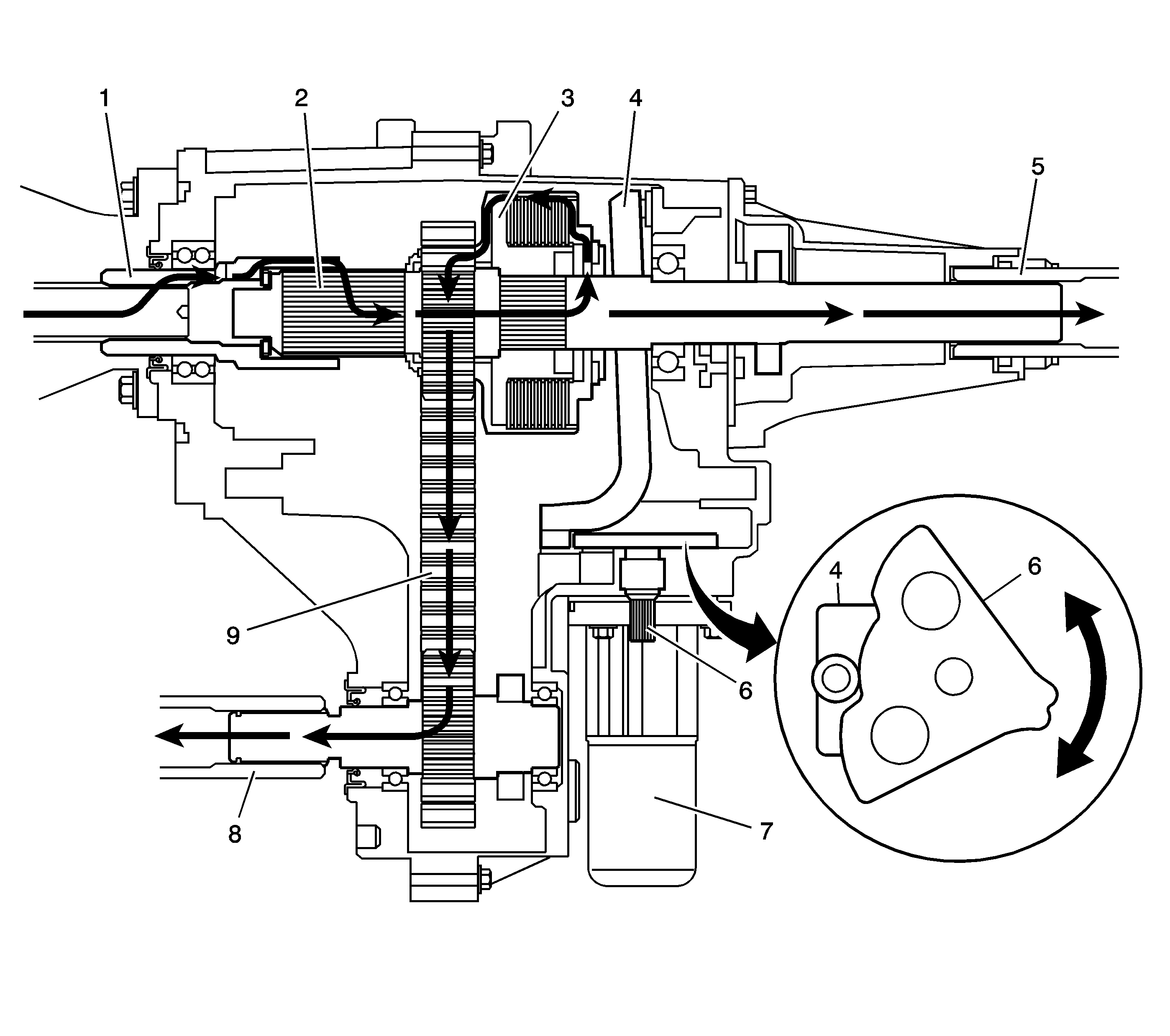
The NVG 126 case halves are high-pressure die-cast aluminum. Ball bearings support the input shaft gear, the front output shaft, and the rear output shaft. A needle bearing is located inside of the input shaft gear to support the front of the rear output shaft. The clutch discs have friction material on one side to prevent warpage. The transfer case requires Auto Trac II Fluid GM P/N 12378508 (Canadian P/N 10953626) which is blue in color. The fluid is designed for smooth clutch application. An oil pump, driven by the rear output shaft, pumps the fluid through the rear output shaft oil gallery to the clutch and bearings.
To drive the rear propshaft (5), the power flows from the transmission to the input shaft gear (1). The input shaft gear (1) is splined to the rear output shaft (2). The power flows from the rear output shaft (2) to the rear propshaft (5).
To drive the front propshaft (8), the clutch hub (3) is splined to the rear output shaft (2). When the transfer case control module commands for more or less clutch torque, the encoder motor (7) turns the control actuator lever shaft (6). The control actuator lever shaft (6) is cam designed, and the cam action moves the clutch lever (4). The clutch lever (4) pivots on the control lever studs and moves toward the clutch apply plate to increase clutch torque. As more pressure is applied to the clutch apply plate, the clutch discs are compressed. Using inner clutch discs, which are engaged with the clutch hub (3), and outer clutch discs, which are engaged with the clutch housing, the power flow is delivered to the clutch housing. The chain drive sprocket is splined to the clutch housing. The power flows from the drive sprocket through the chain (9), to the chain driven sprocket. The driven sprocket is splined to the front output shaft (8). The power flow is delivered to the front propshaft through the front output shaft (8).
Transfer Case Shift Control Module
The transfer case shift control module uses the VIN information for calculations that are required for the different calibrations used based on axle ratio, transmission, tire size, and engine. The system does not know which calibration to use without this information. The transfer case shift control module monitors the speed of the front and rear propshafts in order to detect wheel slippage. When wheel slippage is detected, the module applies a clutch pack contained in side the transfer case. This clutch pack is used to lock-in and apply the front propshaft, transferring torque to the front wheels. The clutch pack is applied by a motor/encoder assembly. When slip is no longer detected by the transfer case shift control module, the clutch is no longer applied.
Transfer Case Motor/Encoder
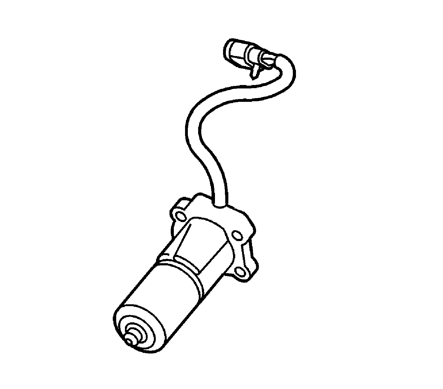
The transfer case Motor/Encoder consists of a permanent magnet (PM) DC motor and gear reduction assembly. It is located on the left hand side (drivers side) of the transfer case. When activated it turns the sector shaft of the transfer case (clockwise or counter clockwise) to apply and release the transfer case clutch pack. The Motor/Encoder is controlled with a pulse width modulated (PWM) signal by the transfer case shift control module. This circuit consists of a Motor Feed A circuit and Motor Control B circuit.
Transfer Case Encoder
The encoder is mounted to the transfer case motor/encoder assembly and is replaced as an assembly. The encoder converts the sector shaft position into an electrical signal input to the transfer case shift control module. The module can detect the location of the transfer case sector shaft by monitoring the voltage returned on the encoder signal circuit.
Transfer Case Speed Sensors
There are three speed sensors on the automatic transfer case (ATC), two on the rear output shaft and one on the front output shaft. Each speed sensor is a permanent magnet (PM) generator. The PM generator produces a pulsing AC voltage. The AC voltage level and number of pulses increases as speed increases.
Vehicle Speed Sensor
One of the two on the rear output shaft is the vehicle speed sensor (VSS) input to the powertrain control module (PCM). The PCM sends this information to the transfer case shift control module via the Class 2 Serial Data bus.
Rear Propshaft Speed Sensor
The transfer case shift control module converts the pulsating AC voltage from the rear transfer case speed sensor to a rear propshaft speed in RPM to be used for calculations. The rear propshaft speed can be displayed with a scan tool.
Front Propshaft Speed Sensor
The transfer case shift control module converts the pulsating AC voltage from the front transfer case speed sensor to front propshaft speed in RPM to be used for calculations, and to monitor the difference between the front and rear sensor speed. It is also used in the AUTO (Adapt) mode of operation to determine the amount of slip and the percent of torque to apply to the front axle. The front propshaft speed can be displayed with a scan tool.
SERVICE AWD Indicator
The SERVICE AWD indicator is an integral part of the cluster and cannot be serviced separately. This lamp is used to inform the driver of the vehicle that a transfer case system malfunction. The SERVICE AWD indicator is controlled by the transfer case shift control module via Class 2.
