Tools Required
J 42640 Steering Column Anti-Rotation Pin
Removal Procedure
- Lock the steering column by installing J 42640 into the underside of the steering column.
- Disconnect the air cleaner intake duct. Refer to Air Cleaner Inlet Duct Replacement in Engine Mechanical - 4.0 L.
- Install the engine support fixture. Refer to Engine Support Fixture in Engine Mechanical - 4.0 L.
- Raise and support the vehicle. Refer to Lifting and Jacking the Vehicle in General Information.
- Remove the front air deflector. Refer to Front Air Deflector Replacement in Body Front End.
- Remove the left front tire and wheel assembly. Refer to Tire and Wheel Removal and Installation in Tires and Wheels.
- Remove the left fascia extension. Refer to Front Bumper Fascia Extension Replacement in Bumpers.
- Remove the intermediate shaft lower pinch bolt.
- Disconnect the intermediate shaft from the power steering gear.
- Support the left side of the frame with an appropriate jack.
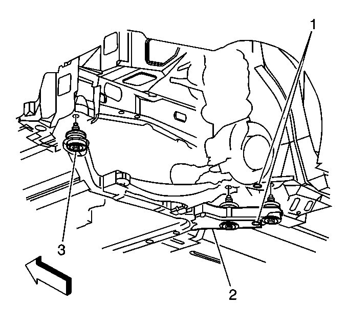
- Remove the three frame-to-body bolts (3) on the left side.
- Carefully lower the left side of the frame and let hang.
- Support the transaxe with an appropriate jack.
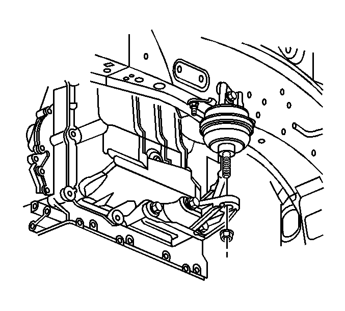
- Remove the lower nut from the left transaxle mount.
- Carefully remove the transaxle jack allowing the transaxle to be supported by the engine support fixture.
- Lower the vehicle enough to gain access to the engine support fixture.
- Using the engine support fixture, carefully lower the transaxle only enough to allow access to the upper nut (2) on the left transaxle mount bracket.
- Raise the vehicle enough to gain access to the left transaxle mount bracket.
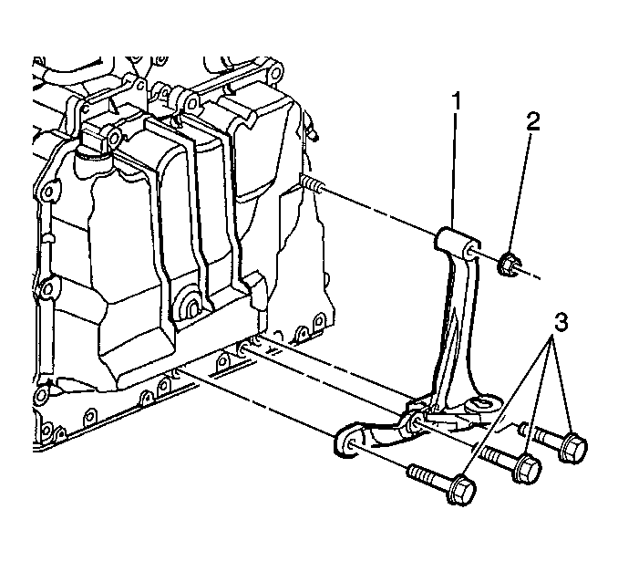
- Remove the nut (2) and the bolts (3) from the bracket.
- Remove the bracket (1).

Notice: The wheels of the vehicle must be straight ahead and the steering column in the LOCK position before disconnecting the steering column or intermediate shaft from the steering gear. Failure to do so will cause the SIR coil assembly to become uncentered, which may cause damage to the coil assembly.
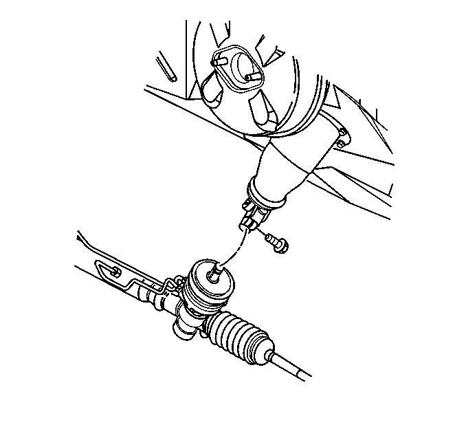
Caution: Failure to disconnect the intermediate shaft from the rack and pinion steering gear stub shaft can result in damage to the steering gear or to the intermediate shaft. This damage may cause loss of steering control, which could result in an accident and possible personal injury.
Important: Insure that all pipes, hoses and wires are clear and not being bound or stressed when lowering the frame.
Important: Insure that all pipes, hoses and wires are clear and not being bound or stressed when lowering the transaxle.
Installation Procedure
- Apply thread lock compound GM P/N 12345493 or equivalent, to the transaxle mount bracket bolts and nut.
- Install the left transaxle mount bracket (1) to the transaxle.
- Install the left transaxle mount bracket bolts (3) and nut (2) .
- Using a suitable transaxle jack. Raise the transaxle to load the left transaxle mount.
- Install the nut onto the left transaxle mount stud.
- Raise the left side of the frame with an appropriate jack.
- Install the three frame-to-body bolts (3) on the left side.
- Connect the intermediate shaft to the power steering gear.
- Install the intermediate shaft lower pinch bolt.
- Install the left fascia extension. Refer to Front Bumper Fascia Extension Replacement in Bumpers.
- Install the Left front tire and wheel assembly. Refer to Tire and Wheel Removal and Installation in Tires and Wheels.
- Install the front air deflector. Refer to Front Air Deflector Replacement in Body Front End.
- Lower the vehicle
- Remove the engine support fixture.
- Connect the air cleaner intake duct. Refer to Air Cleaner Inlet Duct Replacement in Engine Mechanical - 4.0 L.
- Remove the steering column locking tool J 42640 from the steering column.
Notice: Use the correct fastener in the correct location. Replacement fasteners must be the correct part number for that application. Fasteners requiring replacement or fasteners requiring the use of thread locking compound or sealant are identified in the service procedure. Do not use paints, lubricants, or corrosion inhibitors on fasteners or fastener joint surfaces unless specified. These coatings affect fastener torque and joint clamping force and may damage the fastener. Use the correct tightening sequence and specifications when installing fasteners in order to avoid damage to parts and systems.
Tighten
Tighten the left transaxle mount bracket bolts (3) and nut (2)
to 50 N·m (37 lb ft).
Tighten
Tighten the left transaxle mount stud nut to 80 N·m (59 lb ft).
Tighten
Tighten the frame-to-body bolts to 112 N·m (83 lb ft).
Caution: When installing the intermediate shaft make sure that the shaft is seated prior to pinch bolt installation. If the pinch bolt is inserted into the coupling before shaft installation, the two mating shafts may disengage. Disengagement of the two mating shafts will cause loss of steering control which could result in personal injury.
Tighten
Tighten the intermediate shaft lower pinch bolt to 45 N·m (33 lb ft).
