Tools Required
| • | J 38820 Valve Stem Seal Remover and Installer |
| • | J 39313 Spark Plug Port Adapter |
| • | J 43059 Valve Retainer Remover/Installer |
| • | J 44211 On-Vehicle Valve Spring Compressor |
| • | J 44214 Flywheel Holder |
Removal Procedure
- Remove the right camshafts. Refer to Camshaft Replacement - Right Side .
- Raise and support the vehicle. Refer to Lifting and Jacking the Vehicle in General Information.
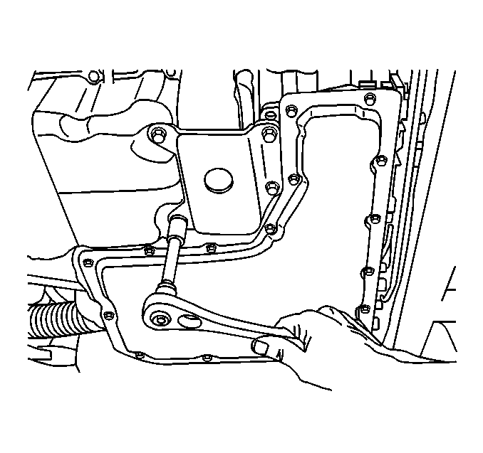
- Remove the brace between the engine oil pan and the transaxle case.
- Remove the torque converter cover. Refer to Torque Converter Cover Replacement in Automatic Transaxle - 4T80-E.
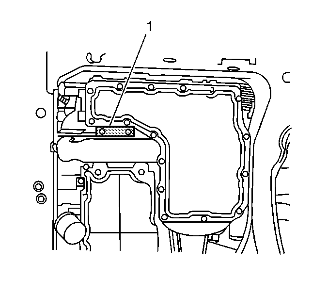
- Install the J 44214 (1).
- Lower the vehicle.
- Remove the spark plug from the cylinder being worked on.
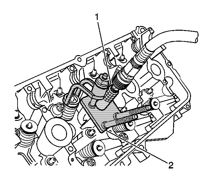
- Install the base plate of the J 44211 (2) over the spark plug hole of the cylinder to be serviced.
- Install the J 39313 (1) in the spark plug hole.
- Apply constant air pressure to the J 39313 (1) in order to keep the valve closed.
- Install the arm and swivel nut of the J 44211 (2) over the stud corresponding to the valve to be serviced.
- Tighten the swivel nut of the J 44211 (2) down only enough to allow access for removal of the valve locks.
- Remove the valve locks. A magnet is the most suitable tool for this activity.
- Loosen the swivel nut of the J 44211 (2) and swing the arm away from the valve spring retainer.
- Remove the valve spring retainer and valve spring.
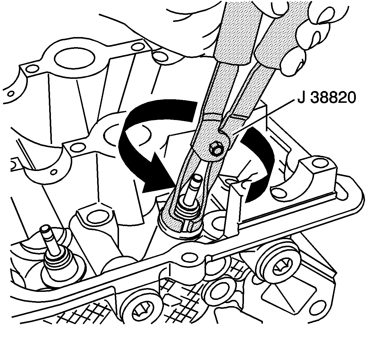
- use the J 38820 in order to grip the seal. Remove the seal by exerting a twisting, pulling motion. Discard the old valve stem seal.
- Inspect and measure the valve spring. Refer to Valve Spring Inspection and Measurement in Engine Mechanical - 4.0 L Unit Repair.


Notice: Clean the spark plug recess area before removing the spark plug. Failure to do so could result in engine damage because of dirt or foreign material entering the cylinder head, or by the contamination of the cylinder head threads. The contaminated threads may prevent the proper seating of the new plug. Use a thread chaser to clean the threads of any contamination.

Caution: Compressed valve springs have high tension against the valve spring compressor. Valve springs that are not properly compressed by or released from the valve spring compressor can be ejected from the valve spring compressor with intense force. Use care when compressing or releasing the valve spring with the valve spring compressor and when removing or installing the valve stem keys. Failing to use care may cause personal injury.

Important: The valve stem seal should not be removed unless replacement is required.
Installation Procedure
- Lubricate the valve stem and the inner diameter of the new seal with clean engine oil.
- Using a twisting pushing motion install the NEW valve stem seal using the J 38820 .
- Install the valve spring retainer and valve spring.
- Swing the arm over the valve spring retainer and tighten the swivel nut of the J 44211 (2) down only enough to allow access for installation of the valve locks.
- Position the valve locks to the valve stem retainer groove using the J 43059 .
- Remove the swivel nut and arm of the J 44211 (2).
- Install the arm and swivel nut of the J 44211 (2) over the stud of any other valves being serviced and repeat removal steps 12 through 17 and installation steps 1 through 7.
- Relieve the air pressure to the cylinder being serviced.
- Remove the J 39313 (1) from the spark plug hole.
- Remove the base plate of the J 44211 (2).
- Install the spark plug. Refer to Spark Plug Replacement in Engine Controls - 4.0 L.
- Repeat removal steps 7 through 17 and installation steps 1 through 11 on any other cylinders being serviced.
- Install the right camshafts. Refer to Camshaft Replacement - Right Side .
- Raise and support the vehicle. Refer to Lifting and Jacking the Vehicle in General Information.
- Remove the J 44214 (1).
- Install the torque converter cover. Refer to Torque Converter Cover Replacement in Automatic Transaxle - 4T80-E.
- Install the oil pan to transaxle brace.
- Lower the vehicle.

Important: Install a seal protector over the valve stem prior to installing the valve stem seal.

Caution: Compressed valve springs have high tension against the valve spring compressor. Valve springs that are not properly compressed by or released from the valve spring compressor can be ejected from the valve spring compressor with intense force. Use care when compressing or releasing the valve spring with the valve spring compressor and when removing or installing the valve stem keys. Failing to use care may cause personal injury.


Notice: Use the correct fastener in the correct location. Replacement fasteners must be the correct part number for that application. Fasteners requiring replacement or fasteners requiring the use of thread locking compound or sealant are identified in the service procedure. Do not use paints, lubricants, or corrosion inhibitors on fasteners or fastener joint surfaces unless specified. These coatings affect fastener torque and joint clamping force and may damage the fastener. Use the correct tightening sequence and specifications when installing fasteners in order to avoid damage to parts and systems.
Tighten
Tighten the oil pan to transaxle brace bolts to 50 N·m (37 lb ft).
