Tools Required
J 38816-A Water Pump Remover/Installer
- Install the water pump and seal using the following procedure:
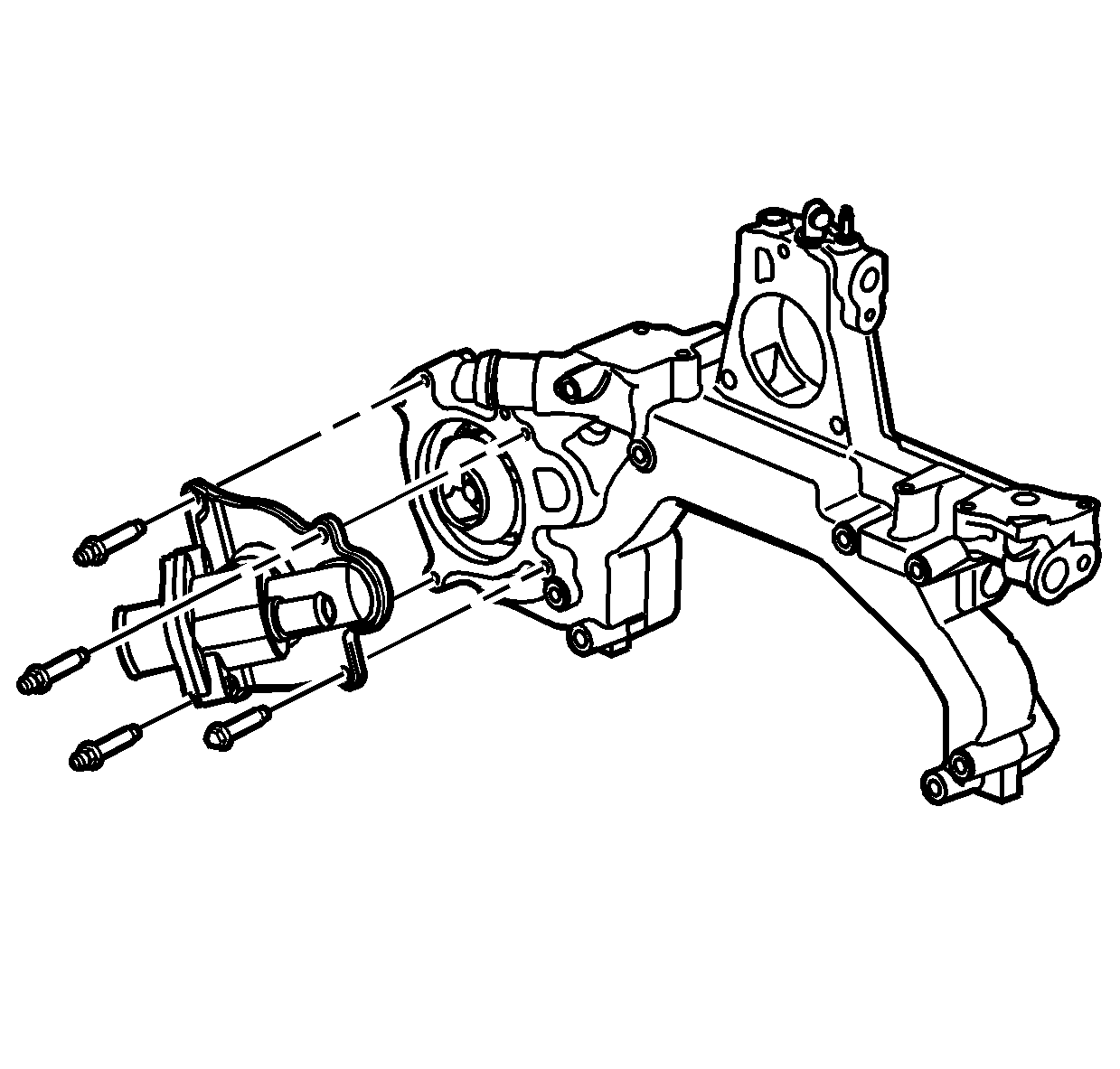
- Install the water pump cover gasket.
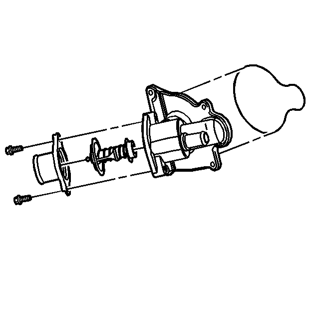
- Install the water outlet and thermostat.
- Install the water outlet bolts.
- Install the water pump cover.
- Install the water pump cover bolt and studs.
- Install the MAP sensor.
- Install the accelerator control cable bracket.
- Install the accelerator control cable bracket bolts.
- Install the throttle body and the NEW plenum duct.
- Install the throttle body bolts.
- Install the EGR gasket.
- Install the EGR valve.
- Install the EGR valve bolts.
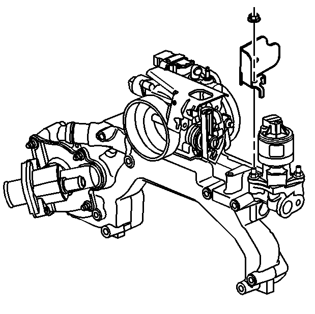
- Install the EGR bracket shield.
- Install the EGR bracket shield nut.
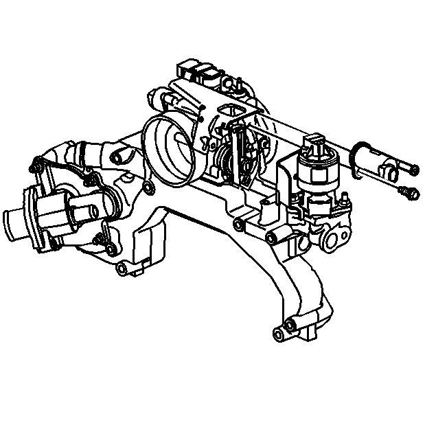
- Install the EVAP emission canister purge valve.
- Install the EVAP emission canister purge valve bolts.
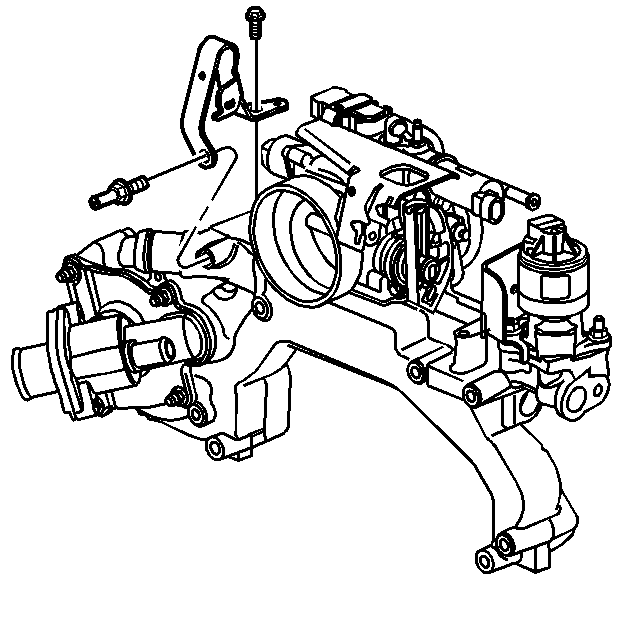
- Install the rear lift bracket.
- Install the rear lift bracket bolt.
- Install the engine coolant outlet fitting.
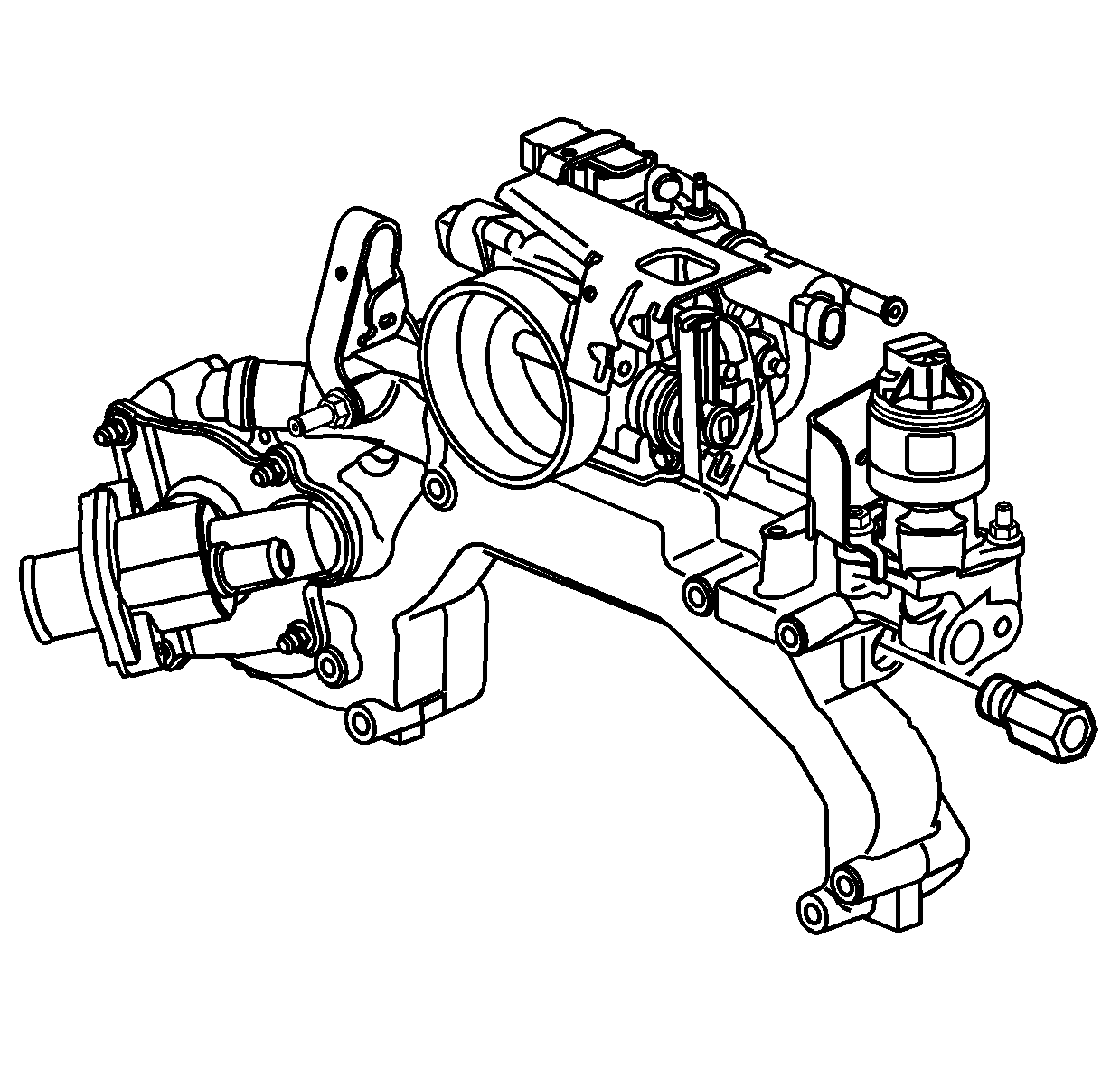
- Install the heater inlet pipe fitting.
Notice: Use the correct fastener in the correct location. Replacement fasteners must be the correct part number for that application. Fasteners requiring replacement or fasteners requiring the use of thread locking compound or sealant are identified in the service procedure. Do not use paints, lubricants, or corrosion inhibitors on fasteners or fastener joint surfaces unless specified. These coatings affect fastener torque and joint clamping force and may damage the fastener. Use the correct tightening sequence and specifications when installing fasteners in order to avoid damage to parts and systems.
| 1.1. | Install the new water pump seal. |
| 1.2. | Place the water pump into the water crossover. Ensure the water pump tabs are correctly indexing the water crossover tabs. |
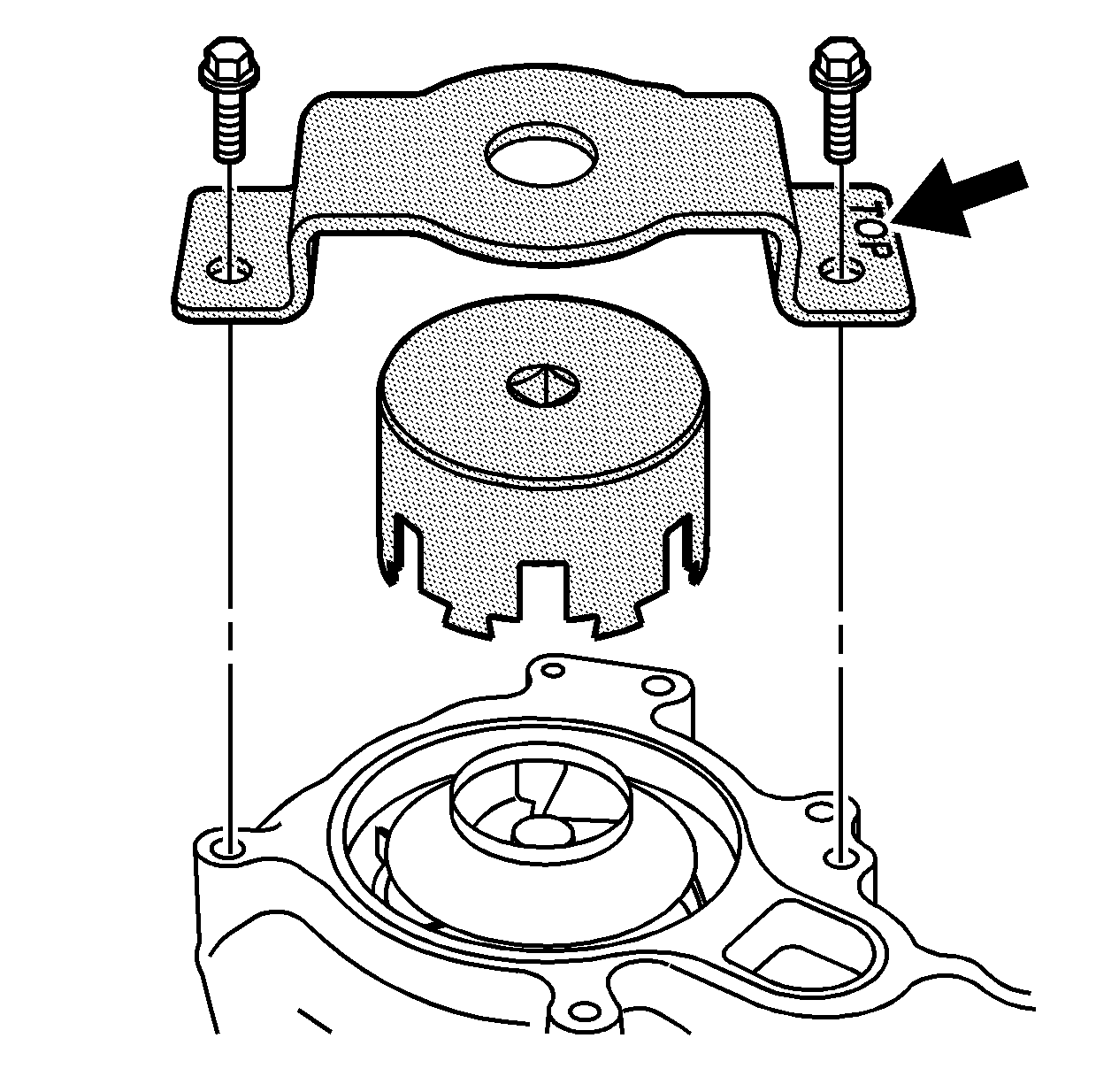
| 1.3. | Index the J 38816-A socket into the water pump. |
| 1.4. | Align the J 38816-A support plate on the water crossover. |
| 1.5. | Install the J 38816-A support plate on the water crossover using the water pump cover bolts. |
| 1.6. | Tighten the water pump in the water crossover by turning the J 38816-A socket counter-clockwise. |
Tighten
Tighten the J 38816-A
socket to 100 N·m (74 lb ft).
| 1.7. | Remove the J 38816-A support plate from the water crossover. |
| 1.8. | Remove the J 38816-A socket. |
Tighten
Tighten the water outlet bolts to 10 N·m (89 lb in).
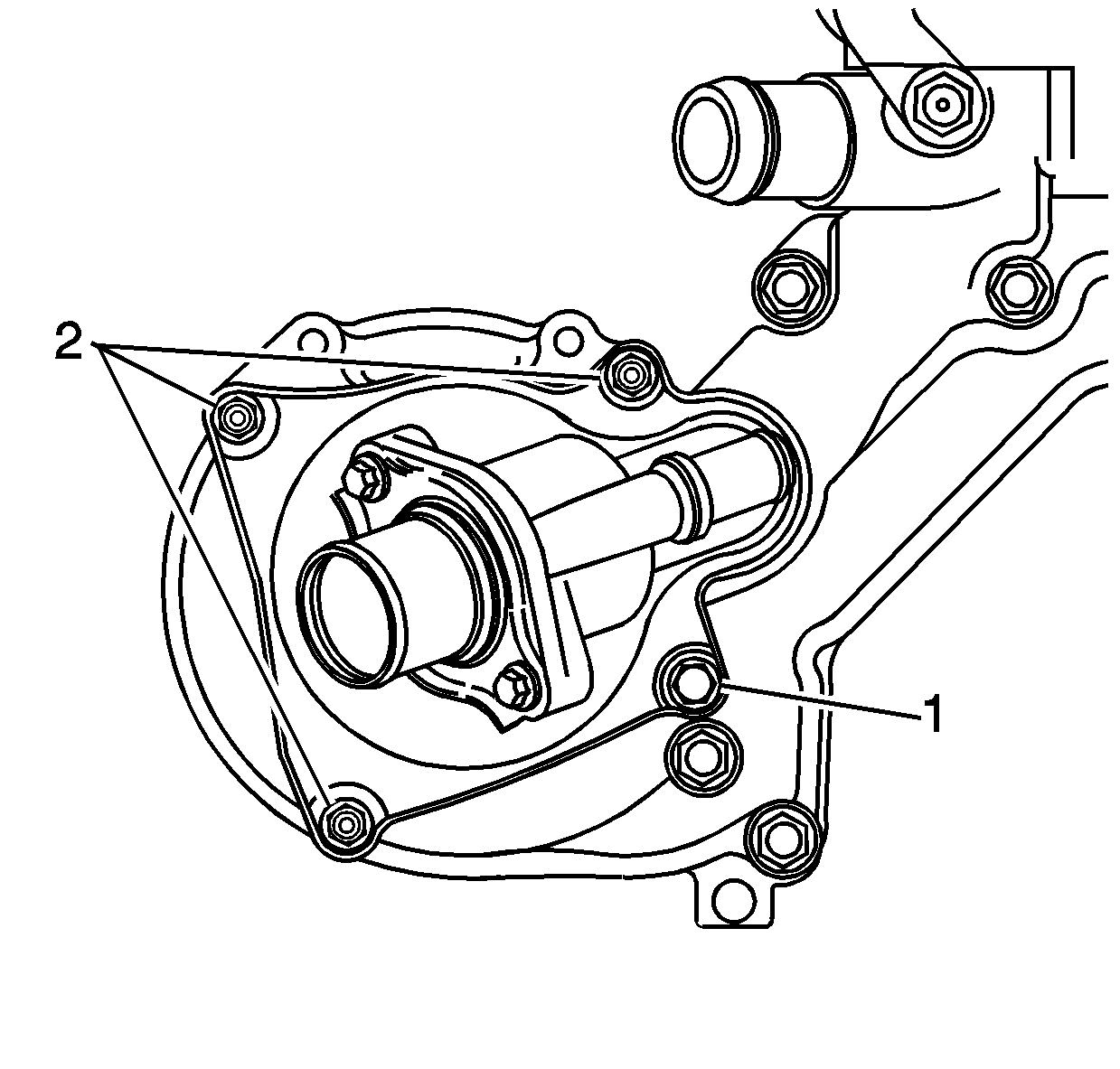
Important: Ensure the bolt is installed in the lower inboard position (1) and the studs are installed in the remaining positions (2).
Tighten
Tighten the water pump cover bolt and studs to 10 N·m (89 lb in).
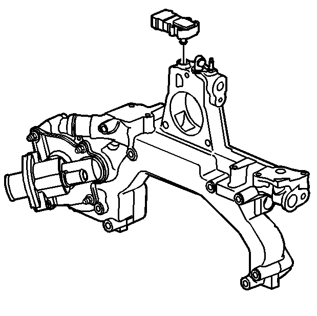
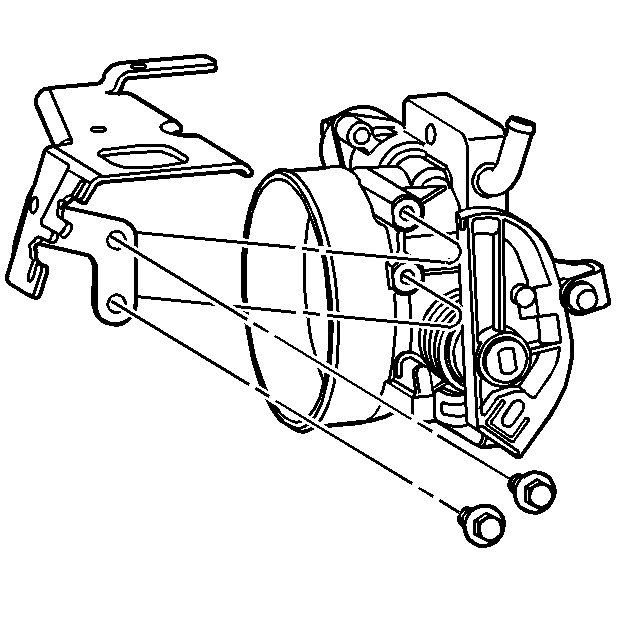
Tighten
Tighten the accelerator control cable bracket bolts to 9 N·m
(80 lb in).
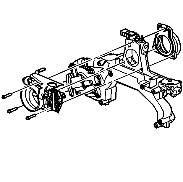
Important: Do not use any type of sealant between the NEW plenum duct and the water crossover.
Tighten
Tighten the throttle body bolts to 10 N·m (89 lb in).
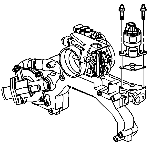
Tighten
Tighten the EGR valve bolts to 24 N·m (17 lb ft).
Tighten
Tighten the EGR bracket shield nut to 10 N·m (89 lb in).
Tighten
Tighten the EVAP emission canister purge valve bolts to 10 N·m
(89 lb in).
Tighten
Tighten the rear lift bracket bolt to 24 N·m (17 lb ft).
Tighten
Tighten the engine coolant outlet fitting to 47 N·m (35 lb ft).
Tighten
Tighten the heater inlet pipe fitting to 40 N·m (30 lb ft).
