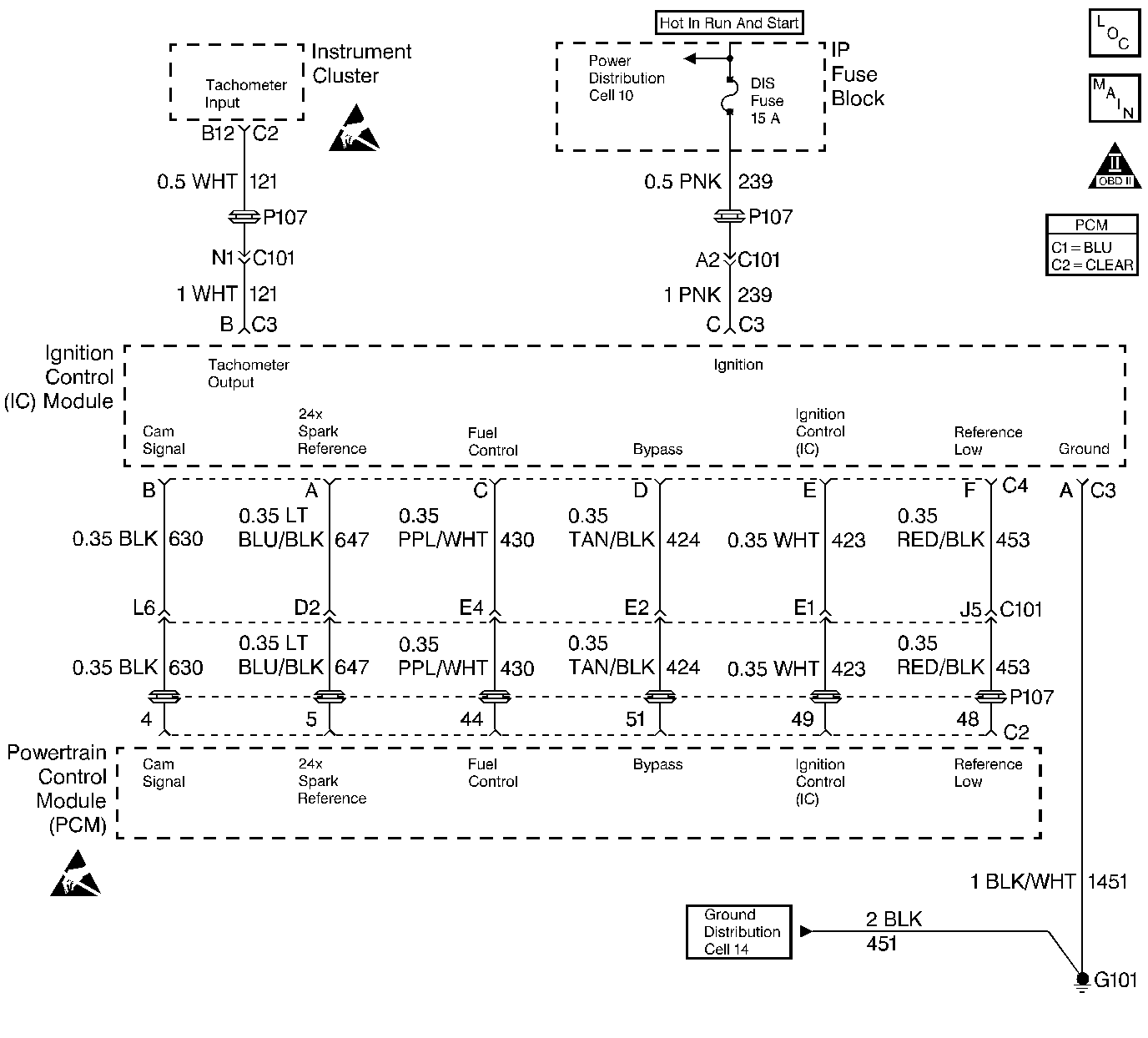
Circuit Description
The diagnostic test checks for an engine stall or near stall and sets DTC P1599 if a stall condition is detected. A partial start where engine RPM exceeds 400 RPM and the engine does not start, will also cause DTC P1599 to set. This DTC is designed to capture snapshot data of the stall condition. This DTC may set as the ignition is turned OFF if the injectors or IC Module lose power before the PCM.
Conditions for Setting the DTC
Test Condition
Ignition turned ON.
Failure Conditions
| • | Engine speed drops below 152 RPM after exceeding 400 RPM this ignition cycle. |
| OR |
| • | No references pulses have been received for 0.75 second after receiving pulses. |
Action Taken When the DTC Sets
| • | The Malfunction Indicator Lamp (MIL) will not illuminate. |
| • | No message will be displayed. |
Conditions for Clearing the DTC
| • | A History DTC will clear after forty consecutive warm-up cycles with no failures of any non-emission related diagnostic test. |
| • | A Last Test Failed (current) DTC will clear when the diagnostic runs and does not fail. |
| • | Use a scan tool to clear DTCs. |
| • | Interrupting PCM battery voltage may or may not clear DTCs. This practice is not recommended. Refer to Clearing Diagnostic Trouble Codes in PCM Description and Operation. |
Diagnostic Aids
Since many things can cause a stalling condition use the snapshot taken of DTC P1599 to compare the values taken when the DTC set to the Typical Scan Data Value table. Look for conditions that could have caused the stall and how long ago the stall occurred.
Test Description
Number(s) below refer to the step number(s) on the Diagnostic Table.
-
If the customer does not have a stall complaint, ignore this DTC.
-
Check for other DTCs that may have caused a stalling condition to occur.
-
This DTC may set during a severe stumble or hesitation. If such is the case, diagnose the condition using the symptom diagnosis charts.
-
This step lists most of the possible causes of stalling arranged by subsystem.
Step | Action | Value(s) | Yes | No | ||||||||
|---|---|---|---|---|---|---|---|---|---|---|---|---|
1 | Was the Powertrain On-Board Diagnostic (OBD) System Check performed? | -- | Go to A Powertrain On Board Diagnostic (OBD) System Check | |||||||||
2 | Is customer complaining of stalling? | -- | Fault not present. Refer to Diagnostic Aids | |||||||||
Turn the key ON. Are any other DTCs set? | -- | Go to DTCs that are set | ||||||||||
Is the display more than the value specified? | 95 kPa | Refer to Symptoms | ||||||||||
Was a fault found and repaired? | -- | Go to Powertrain Control Module Diagnosis for Verify Repair | ||||||||||
6 |
Did any of the checks above require a repair? | -- | Go to Powertrain Control Module Diagnosis for Verify Repair | Refer to Diagnostic Aids |
