Circuit Description
This diagnostic test checks for more than forty nine 24X reference pulses between CAM pulses. However, the number of 24X pulses is allowed to vary between 47 and 49, as long as any variances toggle between too few pulses, and too many pulses. If two variances don't toggle, i.e. they both had 49 reference pulses and eight 4X reference pulses were received between CAM events, then DTC P0371 is set because too many 24X pulses were received.
Conditions for Setting the DTC
Test Conditions
| • | DTC P1376 not set. |
| • | At least one CAM pulse received in the last 0.25 second. |
| • | Engine speed between 496 and 3500 RPM. |
| • | Number of CAM edges since key ON is 7 or greater. |
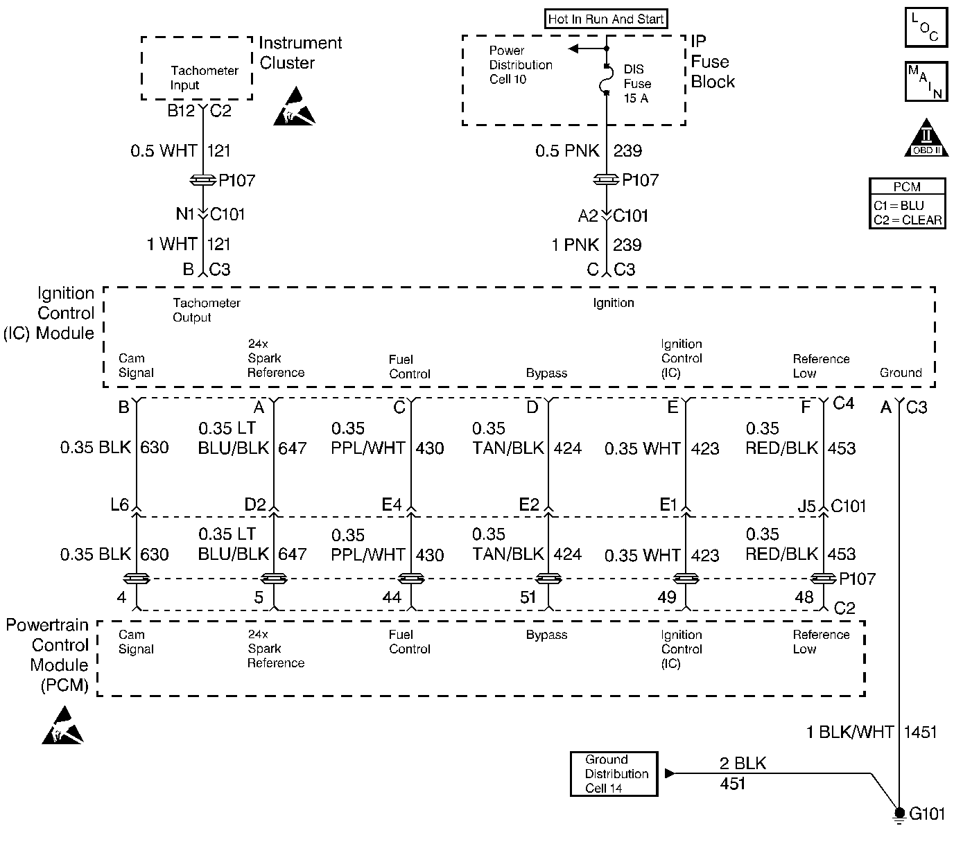
| • | 8 4X reference pulses seen between cam pulses. |
Failure Conditions
| • | More than 49 24X pulses seen between CAM pulses. |
| OR |
| • | The last 24X variance was 49 and current number of 24X pulses received is 49. |
Action Taken When the DTC Sets
| • | The PCM will illuminate the malfunction indicator lamp (MIL) when the diagnostic runs and fails. |
| • | The PCM will record operating conditions at the time the diagnostic fails. This information will be stored in the Freeze Frame and Failure Records. |
Conditions for Clearing the MIL/DTC
| • | The PCM will turn the MIL OFF after three consecutive drive trips that the diagnostic runs and does not fail. |
| • | A Last Test Failed (current) DTC will clear when the diagnostic runs and does not fail. |
| • | A History DTC will clear after forty consecutive warm-up cycles with no failures of any emission related diagnostic test. |
| • | Use a scan tool to clear DTCs. |
| • | Interrupting PCM battery voltage may or may not clear DTCs. This practice is not recommended. Refer to Clearing Diagnostic Trouble Codes in PCM Description and Operation. |
Test Description
Number(s) below refer to the step number(s) on the Diagnostic Table.
-
Checking for possible cause of noise (extra 24X pulses) on the 24X spark reference circuit.
-
If DTC resets, fault is still present. If DTC does not reset, fault has been eliminated.
-
Checking for poor terminal contact at the IC module or PCM that may cause the DTC to set.
Step | Action | Value(s) | Yes | No | ||||||||
|---|---|---|---|---|---|---|---|---|---|---|---|---|
1 | Was the Powertrain On-Board Diagnostic (OBD) System Check performed? | -- | Go to A Powertrain On Board Diagnostic (OBD) System Check | |||||||||
Check for possible sources of EMI (Electromagnetic Interference). Possible causes include the following:
Are any possible sources of EMI found? | -- | Remove source of EMI | ||||||||||
Clear DTCs and retest. Does DTC P0371 reset? | -- | Fault not present | ||||||||||
Was terminal contact repaired? | -- | Go to Powertrain Control Module Diagnosis for Verify Repair | ||||||||||
5 | Replace the Ignition Control module. Refer to Ignition Control Module Replacement (Assembly) . Is the replacement complete? | -- | Go to Powertrain Control Module Diagnosis for Verify Repair | -- |
