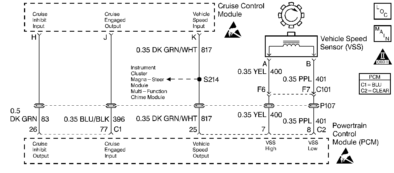
Circuit Description
The PCM will not allow cruise control operation under certain conditions, for example, vehicle speed is too low. This is done by the PCM grounding the 12 volt cruise inhibit signal (CKT 83) sent by the cruise control module. If the PCM is allowing cruise operation and the customer requests cruise, the cruise control module will ground the cruise engaged signal (CKT 396) to the PCM. This diagnostic is used to compare the cruise inhibit output versus the cruise engaged input. If the PCM sees that the cruise control module is signaling that it is engaged by grounding CKT 396 while the PCM is inhibiting cruise operation on CKT 83, DTC P1554 will set.
Conditions for Setting the DTC
Test Condition
The PCM is sending out a cruise inhibit signal.
Failure Condition
The PCM monitors a signal that cruise is engaged.
Action Taken When the DTC Sets
| • | The Malfunction Indicator Lamp (MIL) will not illuminate. |
| • | No message will be displayed. |
Conditions for Clearing the DTC
| • | A History DTC will clear after forty consecutive warm-up cycles with no failures of any non-emission related diagnostic test. |
| • | A Last Test Failed (current) DTC will clear when the diagnostic runs and does not fail. |
| • | Use a scan tool to clear DTCs. |
| • | Interrupting PCM battery voltage may or may not clear DTCs. This practice is not recommended. Refer to Clearing Diagnostic Trouble Codes in PCM Description and Operation. |
Diagnostic Aids
Both the Cruise Engaged and the Cruise displays can be monitored at the same time to aid in diagnosing an intermittent fault.
Clear the DTC and operate the vehicle under the conditions in which the DTC set if a fault condition is suspected.
Reviewing the Failure Rec. may help diagnose an intermittent failure by showing how long ago and under what conditions the DTC set.
Test Description
Number(s) below refer to the step number(s) on the Diagnostic Table.
-
Checking if the PCM is correctly reading signal voltage.
-
Checking for short on the Cruise Engaged Input circuit.
Step | Action | Value(s) | Yes | No |
|---|---|---|---|---|
1 | Was the Powertrain On-Board Diagnostic (OBD) System Check performed? | -- | Go to A Powertrain On Board Diagnostic (OBD) System Check | |
2 | Using a scan tool check the DTC Status. Is DTC P1654 also set? | -- | Go to DTC P1654 Cruise Control Inhibit Output Circuit | |
Has DTC P1554 failed this ignition?. | -- | Fault not present. Refer to Diagnostic Aids | ||
4 |
Has DTC P1554 failed this ignition? | -- | ||
Is the resistance less than the value specified? | 10K ohms | |||
6 | Repair the short to ground on the Cruise Engaged Input circuit. Is the repair complete? | -- | Go to Powertrain Control Module Diagnosis for Verify Repair | -- |
7 | Replace the Cruise Control Module. Is the repair complete? | -- | Go to Powertrain Control Module Diagnosis for Verify Repair | -- |
8 | Replace the PCM. Refer to PCM Replacement/Programming . Is the repair complete? | -- | Go to Powertrain Control Module Diagnosis for Verify Repair | -- |
