GM Service Manual Online
For 1990-2009 cars only

Information Sensors Description

Engine Coolant Temperature (ECT) sensor

The Engine Coolant Temperature (ECT) sensor is a thermistor (a resistor which changes value based on temperature) mounted in the engine coolant stream. Low coolant temperature produces a high resistance (100,000 ohms at -40°C/-40°F), while high temperature causes low resistance (70 ohms at 130°C/266°F).

The PCM supplies a 5 volt signal to the ECT sensor through a resistor in the PCM and monitors the terminal voltage. Since this forms a series circuit to ground through the ECT sensor, high sensor resistance (low temperature) will result in high PCM terminal voltage. When the ECT sensors resistance is low (high temperature), the terminal voltage will be drawn lower. This terminal voltage indicates engine coolant temperature to the PCM.

A hard fault in the ECT sensor circuit should set either a DTC P0117 or P0118. An intermittent failure in the ECT sensor circuit should set either a P1114 or P1115. Remember, these DTCs indicate a fault in the engine coolant temperature circuit, so proper use of the DTC table will lead to either repairing a wiring problem or replacing the sensor, to properly repair a problem.

Heated Oxygen Sensors (HO2S)

Four oxygen sensors are mounted in the exhaust system where they monitor the oxygen content in the exhaust stream. There is an oxygen sensor mounted in each exhaust manifold and one on each end of the catalytic converter. The oxygen sensor located in the front exhaust manifold is the Bank 2 Sensor 1 (Front) sensor. The oxygen sensor located in the rear exhaust manifold is the Bank 1 Sensor 1 (Rear) sensor. The oxygen sensor located in the Y-pipe ahead of the catalytic converter is the Bank 1 Sensor 2 (Pre-converter) sensor. The oxygen sensor located in the catalytic converter outlet is the Bank 1 Sensor 3 (Post-converter) sensor.

An oxygen sensor acts like a battery because it creates its own signal voltage once it reaches operating temperature. This voltage is produced when the oxygen content in the exhaust stream is different than the oxygen content in the atmosphere. A lean condition (high oxygen content in exhaust) will produce a low voltage (near 0 volt) and a rich condition (low oxygen content in exhaust) will produce a high voltage (near one volt). The PCM provides a reference signal voltage (0.45 volt) and a ground to the sensor. The PCM reference voltage is necessary because the oxygen sensors do not provide their own voltage until they reach operating temperature.

The oxygen sensors also incorporate a heating element inside of the sensor housing. This heating element is energized with the ignition On and allows the sensors to reach operating temperatures quickly. The PCM can then use oxygen sensor information sooner after engine startup.

The PCM uses oxygen sensor information during Closed Loop operation to constantly adjust fuel control to reduce exhaust emissions. Because the oxygen sensors provide information sooner after engine startup, exhaust emissions are reduced. Faulty oxygen sensors will cause various driveability conditions and will set a DTC.

Mass Air Flow (MAF) Sensor
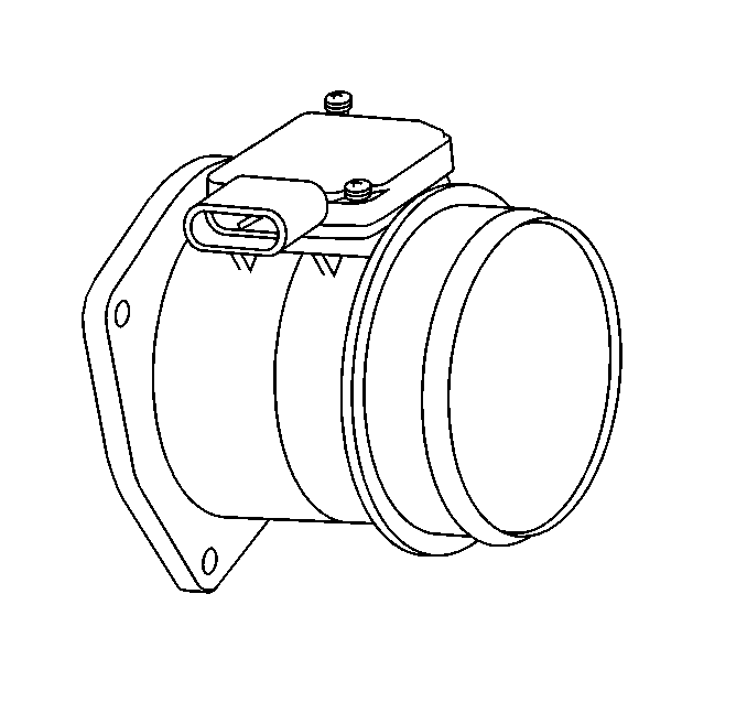

Object Number: 14079  Size: SH

The MAF sensor used on this vehicle is a hot wire type and is used to measure air flow rate (mass/unit time). The MAF sensor output is a variable frequency square wave based on air mass traveling through the sensor. A low frequency output signal from the MAF sensor indicates low air flow and high frequency indicates high air flow. The MAF sensor has two wires crossing the air stream through it. One senses ambient temperature and the other, the hot wire, is kept at a fixed temperature above the ambient temperature. The MAF sensor senses air flow by measuring the power necessary to keep the hot wire hot, which is proportional to air flow, and converts it to a frequency modulate output signal.

The Mass Air Flow (MAF) sensor is located between the intake air duct and the throttle body. It senses the amount of air entering the intake manifold. This information is required by the PCM to control fuel and emissions.

Intake Air Temperature (IAT) sensor

The IAT sensor is a thermistor (a resistor which changes value based on temperature) mounted inside of the air cleaner housing and measures the air temperature entering the engine. At cold air temperatures, the IAT sensor resistance is high and at hot air temperatures, the resistance of the sensor is low. The PCM supplies a 5 volt reference signal and a ground to the sensor and measures the voltage signal as it is changed by the sensor. The voltage is close to 5 volts at cold temperatures and close to zero volt at hot temperatures.

Manifold Absolute Pressure (MAP) Sensor
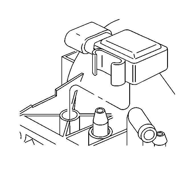

Object Number: 15037  Size: SH

The MAP sensor is mounted on top of the intake manifold and measures the changes in intake manifold pressure which result from engine speed and load changes. The PCM supplies a 5 volt reference signal and a ground to the sensor and the sensor outputs another voltage signal that is proportional to the pressure signal. A high pressure (low vacuum) will produce a signal close to 5 volts and a low pressure (high vacuum) will produce a signal under one volt. The PCM scales the MAP sensor signal in kilo-Pascals (kPa). The MAP signal is the Inverse of what is read on a vacuum gage. When the MAP value is high, intake vacuum with a vacuum gage will be low.

The PCM uses MAP information for EGR control and diagnostics. MAP information is also used to determine barometric pressure and for ignition control. A faulty MAP sensor may cause various driveability conditions and should set a DTC.

Throttle Position (TP) Sensor
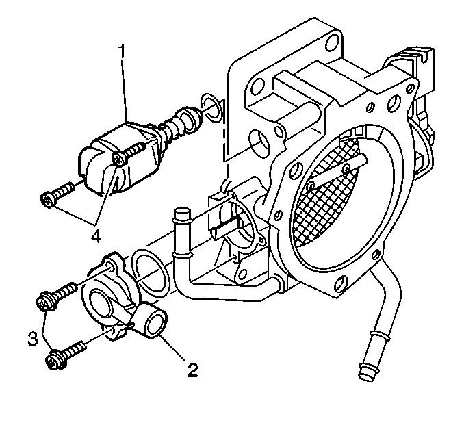

Object Number: 18398  Size: SH
(1)Valve Assembly-Idle Air Control (IAC)
(2)Sensor-Throttle Position (TP)
(3)Screw-TP Sensor Attaching
(4)Screw-IAC Valve Attaching

The TP sensor is a potentiometer that is mounted on the throttle body and provides the PCM with information on throttle valve angle. The PCM provides a 5 volt reference signal and a ground to the TP sensor and the sensor returns a signal voltage that changes with throttle valve angle. At closed throttle (close to 0 degrees) the TP sensor output signal is low (below 1 volt) and at WOT (greater than 80 degrees) the TP sensor output signal is high (above 4 volts). Because the TP sensor is not adjustable, the PCM must account for build tolerances that could affect the TP sensor output at closed throttle. The PCM uses a learning process so that it can correct for variations of up to 6 degrees of throttle angle.

The PCM uses TP information to modify fuel control based on throttle valve angle. For example, power enrichment occurs when the throttle angle approaches WOT. Acceleration enrichment occurs when the throttle angle increases rapidly (similar to an accelerator pump on a carburetor). A faulty TP sensor may cause various driveability conditions and should set a DTC.

Varying octane levels in gasoline can cause detonation in high performance engines. Detonation is sometimes called spark knock. Spark knock causes the pistons and rings to vibrate and rattle producing the spark knocking sound.

To control spark knock a Knock Sensor (KS) is used. This system is designed to retard spark timing to reduce spark knock in the engine. This allows the engine to use maximum spark advance to improve driveability and to improve fuel economy.

The Knock Sensor (KS) system has two major components:

    •  The KS module.
    •  The Knock Sensor (KS).

The knock sensor is mounted into the engine block under the intake manifold. The knock sensor produces an AC voltage which increases with the severity of the knock. This signal voltage inputs to the Powertrain Control Module (PCM). The PCM then adjusts the Ignition Control (IC) to reduce spark knocking.

EVAP Purge Vacuum Switch


Object Number: 15038  Size: SH
(1)EVAP Canister Purge Vacuum Switch
(2)EVAP Canister Purge Solenoid
(3)EVAP Hose

The purge vacuum switch is a normally open switch which closes when vacuum is applied. It is an input to the PCM to signal that the EVAP solenoid has opened, allowing manifold vacuum to draw fuel vapors from the charcoal canister into the intake manifold.

EGR Pintle Position Sensor

The PCM monitors the EGR valve pintle position input to ensure that the valve responds properly to commands from the PCM and to detect a fault if the pintle position sensor and control circuits are open or shorted. If the PCM detects a pintle position signal voltage outside the normal range of the pintle position sensor, or a signal voltage than is not within a tolerance considered acceptable for proper EGR system operation, the PCM will set a DTC.

Brake Switches

This vehicle is equipped with two brake switches each containing multiple sets of contacts and performing several functions. Both switches are located under the left hand side of the I/P on the brake pedal support.

Torque Converter Clutch (TCC) Brake Switch

The Torque Converter Clutch (TCC) Brake Switch contains two sets of (normally closed) electrical contacts referred to as the Torque Converter Clutch (TCC) Brake and Extended Travel Brake Switch contacts. The TCC brake switch contacts provide brake status to the PCM for torque converter clutch control. The extended travel brake switch contacts are used in Torque Management to determine whether the brakes are applied.

Stop/BTSI/Cruise Brake Switch

The Stop/BTSI/Cruise Brake Switch contains three sets of electrical contacts. Two sets of contacts are normally closed and one set is normally open. The one normally open set of contacts is referred to as the stop lamp switch contacts and supplies power to the stop lamps when the brakes are applied. One set of normally closed contacts is referred to as the BTSI brake switch contacts and supplies power to the BTSI solenoid when the brakes are not applied. The other normally closed set of contacts is referred to as the cruise brake switch contacts and is used to disengage cruise when the brakes are applied.

Vehicle Speed Sensor (VSS)


Object Number: 11791  Size: SH
(1)Vehicle Speed Sensor (VSS) Screw
(2)VSS
(3)VSS Seal

The VSS is a pulse generator mounted in the transaxle. A reluctor ring rotates near a magnetic pickup which produces a varying voltage signal in the pickup coil. This voltage signal varies in proportion to vehicle speed and is sent to the PCM, where it is converted to mph.

The PCM uses VSS information for fuel economy calculations, cruise control, idle speed control, transaxle shifts, and to control fuel under certain conditions. A faulty VSS may cause various transaxle and engine driveability conditions and will set a PCM DTC. Refer to SECTION 7.

SMCC Cruise Control Engaged Input

The stepper motor cruise control module sends the cruise status input to the PCM to indicate when cruise control is engaged. The PCM monitors the cruise status signal while commanding cruise to be disengaged via the cruise inhibit circuit. Any of the following conditions may cause the PCM to inhibit cruise control operation:

    •  Engine not running long enough for cruise control operation.
    •  Transaxle range inputs indicate park, neutral, low, or reverse gear selected.
    •  Engine speed is too high or too low.
    •  Vehicle speed is too high or too low.
    •  Traction is active.
    •  Vehicle acceleration or deceleration rate is too high.

Power Steering Pressure (PSP) Switch

The power steering pressure switch is located on the power steering pressure hose between the power steering pump and rack and pinion gear. The power steering pressure switch is normally closed and provides a battery voltage signal to the PCM with no power steering load. When power steering pressure increases to a calibrated level due to steering load (such as full steering lock), the switch opens and causes the signal voltage to the PCM to drop to 0 volts.

The PCM uses the power steering pressure switch signal for idle speed control during high steering loads to maintain a stable idle. A shorted power steering pressure switch may cause a stumble or stall during steering loads and an open switch should set a PCM DTC.

Information Sensors A/C Inputs

A/C Request Signal

This signal indicates to the PCM that an A/C mode is selected at the A/C control head. The PCM uses this information to adjust the idle speed before turning 'ON' the A/C compressor clutch. If this signal is not Available to the PCM, the A/C compressor will be inoperative.

A/C High Refrigerant Pressure Switch

The A/C High Refrigerant Pressure Switch is located in the compressor discharge line and monitors the compressor discharge pressure. This switch acts as a safeguard to prevent refrigerant 'blow off' from the compressor pressure relief valve and Disengages the compressor in the case where refrigerant pressure is above 2965 kPa (430 psi).

A/C Low Refrigerant Pressure Switch

The A/C Low Refrigerant pressure switch is located in the low pressure refrigerant line. When pressurized, the switch is closed and allows the compressor clutch relay to energize, feeding battery voltage to the compressor clutch coil. If the pressure drops below 2 psi, the switch opens and cuts off voltage to the clutch.

A/C High Refrigerant Temperature Sensor

The high Refrigerant Temperature sensor is located in the high pressure refrigerant liquid line between the condenser and orifice tube. By monitoring the refrigerant temperature, the PCM can determine the pressure based upon the pressure-temperature relationship of R-134a.

A/C Low Refrigerant Temperature Sensor

The A/C Low Refrigerant Temperature Sensor is located in the low pressure refrigerant line between the orifice tube and evaporator. The PCM monitors this sensor to determine the low side pressure based upon the pressure-temperature relationship of R-134a.

Information Sensors Graphs

Engine Coolant Temperature (ECT) Sensor


Object Number: 15039  Size: MH

The ECT sensor is a thermistor (a resistor that changes value due to temperature) mounted in the engine coolant flow. High coolant temperatures result in low resistance and low temperatures result in high resistance. The PCM provides a 5 volt reference signal and a ground to the ECT sensor, and it measures the voltage signal as it changes due to the sensors resistance. A high coolant temperature will result in low signal voltage (near 0 volt) and low coolant temperature will result in high signal voltage (near 5 volts).

The ECT sensor circuit uses two different temperature sensing circuits for two temperature ranges - below 50°C (122°F) and above 50°C (122°F). The PCM will shift between a high resistance circuit for low temperatures and a low resistance circuit for high temperatures.

Intake Air Temperature (IAT) Sensor


Object Number: 15040  Size: MH

The IAT sensor is a thermistor (a resistor that changes value with temperature) mounted in the intake air stream and it measures changes in the temperature of air entering the engine. High air temperatures result in low resistance and low air temperatures result in high resistance. The PCM provides a 5 volt reference signal and a ground to the IAT sensor. The PCM measures the voltage changes in the signal due to the sensors resistance. A high air temperature will result in low signal voltage (near 0 volt) to the PCM and low air temperature will result in high signal voltage (near 5 volt).

Manifold Absolute Pressure (MAP) Sensor


Object Number: 15041  Size: MH

The MAP sensor is a potentiometer that is mounted inside the intake manifold and measures the changes in intake manifold pressure due to engine speed and load changes. The PCM supplies a 5 volt reference signal and a ground to the MAP sensor and the sensor in turn sends a voltage signal to the PCM. As manifold pressure increases (vacuum decreases), the voltage signal increases and as manifold pressure decreases (vacuum increases), the voltage signal decreases. A high pressure signal will be close to 5 volts and a low pressure signal will be close to 0 volt.

Mass Air Flow (MAF) Sensor


Object Number: 15042  Size: MH

The MAF sensor is an electronic device that measures air flow into the intake manifold. The MAF sensor is mounted to the throttle body. The MAF sensor is supplied battery voltage and a ground. The MAF sensor in turn sends a frequency signal to the PCM. As air flow increases, the signal frequency increases and as air flow decreases, the signal frequency decreases. A high flow signal will be close to 9000 Hertz and a low flow signal will be close to 2000 Hertz.

Throttle Position (TP) Sensor


Object Number: 15043  Size: MH

The TP sensor is a potentiometer that is mounted on the throttle body to measure changes in throttle valve angle. The PCM provides a 5 volt reference signal and a ground to the TP sensor and the sensor in turn sends a voltage signal representing throttle position back to the PCM. As the throttle angle increases, the voltage signal increases and as the throttle angel decreases the voltage signal decreases. A closed throttle angle will result in a voltage signal near 0 and wide open throttle will produce a signal near 5 volts.