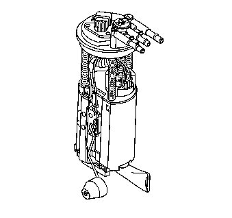
Fuel Sender Assembly Replacement Replacement
Removal Procedure
Tools Required
J 39765 Fuel Sender Locknut Wrench
Notice: Do Not handle the fuel sender assembly by the fuel pipes. The amount of leverage generated by handling the fuel pipes could damage the joints.
Important: Always replace the fuel sender O-rings when reinstalling the fuel sender assembly.
- Relieve the fuel system fuel pressure. Refer to the Fuel Pressure Relief Procedure 4.0L, Fuel Pressure Relief , 3.8L.
- Drain the fuel tank to no more than 1/4 of a tank full. Refer to Fuel Tank Replacement (Draining Fuel Tank) 4.0L, Fuel Tank Draining , 3.8L.
- Remove the spare tire cover, the jack, and the spare tire.
- Remove the rear compartment trim. Refer to Body Rear End.
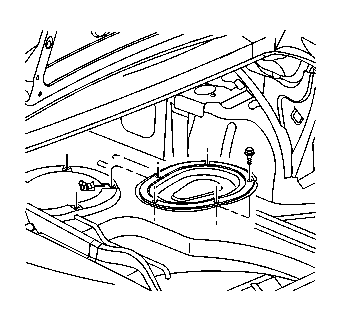
- Remove the fuel sender access panel bolts from the fuel sender access panel.
- Remove the quick-connect fittings at the fuel sender assembly. Refer to Servicing Quick Connect Fittings 4.0L, Servicing Quick Connect Fittings , 3.8L.
- Remove the electrical connector at the fuel sender.
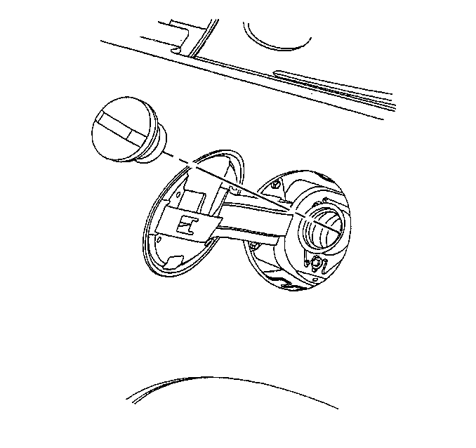
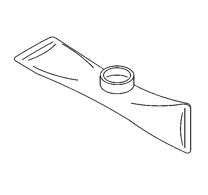
- Remove the fuel sender retaining ring using the J 39765 Fuel Sender Spanner Wrench.
- Pull the modular fuel sender straight up while pumping the fuel from the reservoir.
- Clean the fuel sender assembly O-ring sealing surfaces.
- Inspect the fuel sender assembly O-ring sealing surfaces.
Important: When removing the modular fuel sender assembly from the fuel tank, the reservoir bucket on the fuel sender assembly is full of fuel. The modular fuel sender assembly must be tipped slightly during removal in order to avoid damage to the float. Place any remaining fuel into an approved container once the modular fuel sender assembly is removed from the fuel tank.
Important: The modular fuel sender assembly will spring-up when the locking ring is removed.
Installation Procedure
- Position the new fuel sender assembly O-ring on the fuel tank.
- Install the fuel sender assembly and the fuel sender assembly retainer cam using the J 39765 Fuel Sender Spanner Wrench.
- Install the quick-connect fittings at the fuel sender assembly. Refer to Servicing Quick Connect Fittings 4.0L, Servicing Quick Connect Fittings , 3.8L.
- Install the negative battery cable.
- Inspect for leaks.
- Install the fuel sender access panel.
- Install the rear compartment trim. Refer to Body Rear End.
- Install the spare tire, the jack, and the spare tire cover.
- Add fuel and install the fuel tank filler pipe cap.
Important: Care should be taken not to fold over or twist the fuel pump strainer when installing the fuel sender assembly, as this will restrict fuel flow. Also, assure that the fuel pump strainer does not block full travel of float arm.
| 5.1. | Turn the ignition switch to the On position for 2 seconds. |
| 5.2. | Turn the ignition switch to the Off for 10 seconds. |
| 5.3. | Turn the ignition switch to the On position. |
| 5.4. | Check for fuel leaks. |
Tighten
Tighten the bolts to 2 N·m (18 lb in).
Fuel Sender Assembly Replacement Serviceable Components
Removal Procedure
Notice: Do Not handle the fuel sender assembly by the fuel pipes. The amount of leverage generated by handling the fuel pipes could damage the joints.
- Relieve the fuel system fuel pressure. Refer to the Fuel Pressure Relief Procedure .
- Drain the fuel tank to no more than 1/4 of a tank full. Refer to Fuel Tank Replacement (Draining Fuel Tank) .
- Remove the fuel sender assembly. Refer to Fuel Sender Assembly Replacement .
Important: The modular fuel sender support assembly will spring-up when the locking ring is moved.
Disassemble Procedure
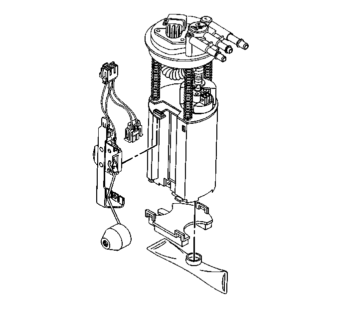
- Note the position of the fuel sender strainer for installation.
- Support the reservoir with one hand and grasp the fuel sender strainer with the other hand.
- Pull the fuel sender strainer off of the fuel pump.
- Inspect the fuel sender strainer. If the fuel sender strainer is contaminated, the fuel tank should be cleaned.
- Discard the fuel sender strainer after inspection.
- Disassemble the rubber pad off of the bottom of the modular fuel sender.
- Disassemble the electrical connectors from the sensor assembly of the fuel pump and the cover assembly.
- Disassemble the fuel level sensor assembly.
Assemble Procedure
- Assemble the fuel level sensor assembly.
- Assemble the electrical connectors to the fuel pump and the cover assembly.
- Assemble the rubber pad on the bottom of the modular fuel sender.
- Position the new fuel sender strainer on the modular fuel sender and push on the outer edge of the fuel sender strainer until the fuel sender strainer is fully seated.
Installation Procedure
- Install the fuel sender assembly. Refer to Fuel Sender Assembly Replacement .
- Add fuel and install the fuel tank filler pipe cap.