GM Service Manual Online
For 1990-2009 cars only

Purpose

The Exhaust Gas Recirculation (EGR) system is used in automotive engines to decrease the emission levels of oxides of nitrogen (NOx). NOx defines a group of chemical compounds containing nitrogen and varying amounts of oxygen that can have harmful environmental effects in large quantities.

NOx forms during the combustion process in amounts that are dependent on the concentration of oxygen in the combustion chamber and the duration that the combustion process temperatures exceed 1500°F. Decreased NOx levels are accomplished by reducing the peak combustion temperatures through dilution of the incoming fuel/air charge with exhaust gas. When combusted, exhaust gas (largely non-reactive carbon dioxide and water vapor) acts to absorb a portion of the combustion energy, resulting in lower temperatures throughout the combustion process and yielding lower amounts of NOx.

Desired amounts of EGR depend upon the geometry of the combustion chamber and the operating condition of the engine. Extensive laboratory and vehicle tests are used to determine optimal EGR rates for all operating conditions. Too little EGR can yield high NOx, while too much EGR can disrupt combustion events. This engine uses a computer controlled valve to precisely regulate the amount of EGR delivered to the engine for all operating conditions.

Operation


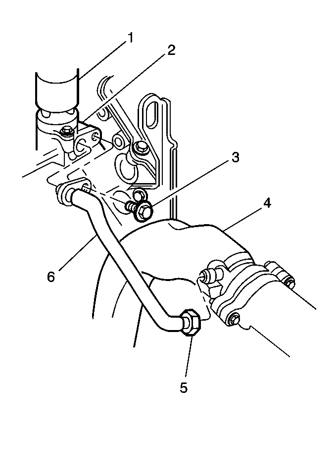
Object Number: 11796  Size: MH
(1)Linear EGR Valve
(2)Water Pump Housing
(3)Bolt
(4)Crossover Exhaust Pipe
(5)Nut
(6)EGR Valve Pipe

Exhaust gases are routed to the engine through the corrugated semi-flexible feed pipe which connects the crossover exhaust pipe to the crossover water pump housing.


Object Number: 11789  Size: MF
(1)EGR Passages
(2)Coolant Pasages
(3)Cylinder Head
(4)Linear EGR Valve
(5)EGR Inlet Pipe
(6)Water Pump Housing
(7)EGR Valve Outlet Pipe

In the crossover water pump housing,as shown in the EGR Flow figure, exhaust gases are precisely metered by the PCM controlled EGR Valve, then cooled by engine coolant and finally routed into the throttle body spacer through another corrugated semi-flexible feed pipe from the water pump crossover. A potential drawback with EGR is that for certain driving schedules, deposits can accumulate when hot exhaust gases are cooled. The system uses the crossover water pump housing as a cross-flow heat exchanger to cool exhaust gases in large easily cleaned passages to virtually eliminate any concern with deposit accumulation during the service life of the engine. This is done by having the cooling passage reduce EGR gasses below their deposit forming temperature prior to routing these gasses into the throttle body spacer.


Object Number: 11699  Size: SH
(1)Linear EGR Valve
(2)Exhaust Gas
(3)To Cylinders
(4)Pintle

Engine vacuum draws exhaust gases through the EGR feed pipe into the throttle body spacer where they mix with the incoming air charge and are distributed equally to each cylinder.

The EGR Valve regulates the amount of exhaust gas fed to the engine. This mixture is dependent upon the height of the pintle above the orifice in the base of the valve.

Object Number: 11696  Size: SH
(1)Cap-Sensor
(2)Sensor-EGR Pintle Position
(3)Pole Piece-Primary
(4)Bobbin and Coil Assembly
(5)Sleeve-Armature
(6)Valve-Pintle
(7)Armature and Base Assembly

The bobbin and coil (solenoid) assembly is encapsulated to maximize reliability, to seal the coil from the environment, and to prevent movement of the coil and terminals. Inside the solenoid (bobbin and coil) assembly is an armature assembly, consisting of a pintle and valve assembly, two seals, retaining washers, a seal spring, an armature spring, and a bearing. The valve pintle shaft is sealed from the exhaust chamber by a bearing. In addition, an armature shield, held in place by a compression spring, deflects exhaust gas from the shaft and the armature. The base adapter and base plate make up the base assembly.

As mentioned above the PCM controlled EGR Valve regulates the amount of exhaust gas fed to the engine. This device offers more precise EGR flow metering than a back pressure or digital type valve and superior emission control and driveability.

Exhaust Gas Recirculation (EGR) Control


Object Number: 15070  Size: MF

The Exhaust Gas Recirculation (EGR) System removes exhaust gas from the exhaust manifold and pipes it back to the combustion chambers, where it can be burned again. This helps to reduce oxides of nitrogen (NOx) emissions, by reducing combustion temperatures. The EGR valve meters the amount of exhaust gas that is allowed to return to the combustion chambers. The PCM controls the EGR valve, dictating when operation begins and ends, along with determining the amount of exhaust gas that can be efficiently recycled. The EGR valve consists of a solenoid, a pintle, and a pintle position sensor. By energizing the solenoid, the PCM causes the pintle to open and allows exhaust gas to pass through the valve. The solenoid is connected to ignition voltage. The PCM controls the solenoid by grounding the control circuit. By switching the ground on and off, the PCM creates a variable pulse width modulated (PWM) signal that opens the pintle at different rates and to different positions.

The pintle position sensor allows the PCM to monitor the actual position of the pintle, thus enabling it to correct pintle position errors. The sensor is a type of potentiometer, or variable resistor, which provides feedback voltage that is proportional to pintle position. The PCM provides the sensor with 5 volts and a ground. The signal circuit provides the feedback to the PCM. Pintle position is measured in counts, from 0 to 255, with 0 being full closed and 255 full open. However, in practice these limits will not be reached. To compensate for this, the PCM computes a normalized pintle position, which will be discussed later.

Enable/Disable Conditions

All of the following conditions must be met before the PCM will allow EGR operation to begin:

  1. Engine running.
  2. PCM in ignition control mode.
  3. Transaxle in drive range.
  4. Intake air temperature between -10°C and 128°C.
  5. If engine coolant temperature (ECT) was between 18°C and 36°C at engine start-up, ECT must be between 18°C and 115°C.
  6. If engine coolant temperature (ECT) was less than 18°C or greater than 36°C at engine start-up, ECT must be between 80°C and 115°C.

  7. Manifold air pressure must be greater than a low limit, between 25 and 34 kPa depending on barometric pressure, and less than 90 kPa.
  8. Engine speed between 800 and 3200 RPM.
  9. Throttle position must be less than a high limit, between 19 degrees and 35 degrees depending on barometric pressure.
  10. Any one of the following conditions met:
  11. •  Vehicle speed less than 36 mph and throttle position switch open.
    •  Vehicle speed less than 36 mph, throttle switch closed.
    •  Vehicle speed 2 MPH or less and throttle position at least 1.4 degrees.
  12. Fuel is not being disabled to any cylinder due to traction control or acceleration reduction.
  13. No engine overtemperature condition is present.
  14. If all of the EGR enable conditions have been met but the PCM determines that A/C clutch engagement is impending, EGR enable will be delayed until 0.15 second after the A/C clutch engages.

Closed Valve Pintle Position

At key-on, the PCM sets the closed valve pintle position to 103 counts. Since the EGR valve pintle will not close to 0 counts, the PCM uses 103 counts as a reference point. The closed valve pintle position is updated only when the actual pintle position falls below 103 counts. If the closed valve pintle position is measured above 103 counts, the PCM will set a diagnostic trouble code. A DTC will also set if the pintle position falls below 9 counts. Closed valve pintle positions outside of this range indicate a pintle position sensor failure. Once the closed valve pintle position is established, the PCM uses this information to calculate the normalized pintle position.

Normalized Pintle Position

After the closed valve pintle position is established, the PCM calculates a normalized pintle position. The normalized position is the difference between the actual pintle position and the closed valve pintle position multiplied by a scaling factor. The PCM uses the normalized pintle position to determine the desired pintle position for maximum EGR performance.

Desired Pintle Position

The desired pintle position is the result of computations performed by the PCM using various inputs such as engine speed, intake manifold temperature and pressure, air flow, and engine coolant temperature, and stored calibrations from the PCM EPROM. By continuously computing the desired pintle position, the PCM can vary EGR flow for particular driving conditions.

The PCM calculates pintle position error, desired pintle position minus normalized pintle position, to determine if it is accurately controlling EGR flow. If the pintle position error exceeds 25 counts for more than 10 seconds, the PCM will set a diagnostic trouble code.

Turning EGR On and Off

When all of the conditions have been met to enable EGR, the PCM calculates the desired pintle position and determines the rate at which it will open or ramp the pintle to its desired position. The ramp rate depends on vehicle speed, A/C clutch status, and outside air temperature. The PCM controls the ramp rate by varying the EGR solenoid duty cycle. The ramp rate is a percentage of desired pintle position and is determined as follows:

    •  If the vehicle speed is greater than 20 mph, the pintle will open at a rate of 5% every 0.05 second.
    •  If the vehicle speed is less than or equal to 20 mph, A/C clutch engagement is not possible, and outside air temperature is at least 41°F, the pintle will open at a rate of 2.3% every 0.05 second.
    •  If the vehicle speed is less than or equal to 20 mph, A/C clutch engagement is possible or outside air temperature is less than 4°F, the pintle will open at a rate of 0.8% every 0.05 second.

The PCM will maintain the same ramp rate until the desired pintle position is reached. When EGR is being ramped on, the PCM will maintain current spark advance. The PCM will ramp the spark to its desired advance once EGR has reached its desired position. This delay is necessary because EGR does not reach all cylinders immediately, and premature spark advance would cause driveability problems.

When EGR is turned off, the PCM will cause the pintle to close at a rate of 6.3% every 0.05 second until the pintle is in the closed position. However, if engine speed is 0 RPM (engine not running), the pintle will be immediately closed.

If EGR status transitions from off to on or on to off during a ramp, the ramp will reverse directions from that point and continue at the normal rate until the desired pintle position is reached.

EGR Diagnosis

Too much EGR flow tends to weaken combustion, causing the engine to run roughly or stop. With too much EGR flow at idle, cruise, or cold operation, any of the following conditions may occur:

    •  Engine stops after cold start.
    •  Vehicle surge.
    •  Engine stops at idle after deceleration or idles rough.

If the EGR valve is stuck open, the engine may not run.

Low or no EGR flow allows combustion temperatures to get too high during acceleration and load conditions. This could cause:

    •  Spark knock (detonation), especially on light acceleration.
    •  Emission test failure.

This powertrain system runs several tests on the EGR system and a fault in the EGR circuits, the flow of the EGR valve or the controllability of the valve should set a PCM DTC.