Circuit Description
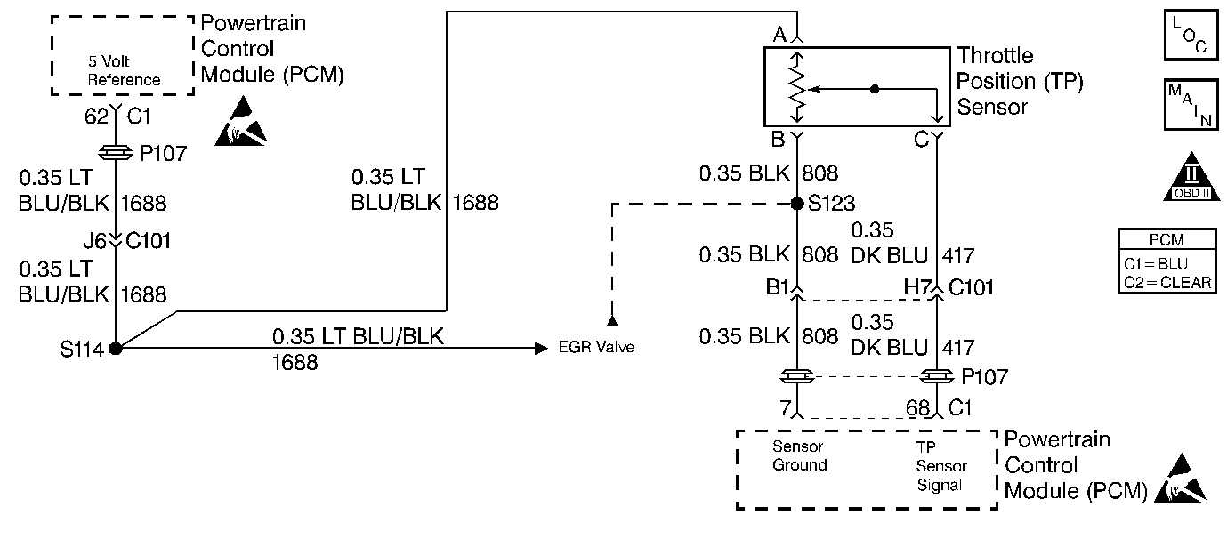
The Throttle Position sensor is a potentiometer. A 5 volt reference is provided on CKT 1688 and ground is provided on CKT 808. The TP sensor signal CKT 417 varies between ground and 5 volts based on the position of the throttle plates. At low throttle angle, the TP sensor signal voltage is low. The PCM uses TP sensor information to determine idle, Wide Open Throttle (WOT), deceleration enleanment and acceleration enrichment. DTC P0123 sets when the PCM detects a TP sensor signal that is too high. The PCM tests the TP sensor feedback every 100 ms. If the TP reading is 4.96 volts or higher DTC P0123 will set.
Conditions for Setting the DTC
Test Condition
Engine speed between 25 and 3000 RPM.
Failure Condition
The TP sensor reading is 4.96 volts or higher.
Action Taken When the DTC Sets
| • | PCM disables the torque converter clutch. |
| • | PCM calculates a TP sensor value based on MAP and engine speed inputs. |
| • | PCM disables fourth gear. |
| • | The PCM will illuminate the malfunction indicator lamp (MIL) when the diagnostic runs and fails. |
| • | The PCM will record operating conditions at the time the diagnostic fails. This information will be stored in the Freeze Frame and Failure Records. |
Conditions for Clearing the MIL/DTC
| • | The PCM will turn the MIL OFF after three consecutive drive trips that the diagnostic runs and does not fail. |
| • | A Last Test Failed (current) DTC will clear when the diagnostic runs and does not fail. |
| • | A History DTC will clear after forty consecutive warm-up cycles with no failures of any emission related diagnostic test. |
| • | Use a scan tool to clear DTCs. |
| • | Interrupting PCM battery voltage may or may not clear DTCs. This practice is not recommended. Refer to Clearing Diagnostic Trouble Codes in PCM Description and Operation. |
Diagnostic Aids
If fault is not present perform Powertrain Ground Check and also review Failure Rec. to determine conditions under which and how long ago the DTC set.
Test Description
Number(s) below refer to the step number(s) on the Diagnostic Table.
-
With TP sensor or wiring shorted, throttle position sensor display will read 4.85 volts or greater.
-
Checking for shorted TP sensor or shorted wiring. If the display value stays greater than 0.1 volts with the TP sensor disconnected, the problem is in the wiring.
-
Checking for a short to voltage on the TP sensor signal circuit. A short to voltage will cause a high TP sensor reading.
-
Checking for a short to voltage in the TP sensor 5 volt reference circuit. The voltage should never be higher than 5.4 volts.
-
Checking for an open in the TP sensor ground circuit between the TP sensor and PCM. An open in the TP sensor ground circuit will cause the TP signal to always be high whenever the TP sensor is connected.
-
A high voltage reading on the 5 volt reference circuit could be caused by a short to voltage on another 5 volt reference circuit, some 5V Ref. circuits are shared inside the PCM, or battery voltage bleeding onto the 5 volt reference circuit as in a defective Linear EGR Valve.
Step | Action | Value(s) | Yes | No |
|---|---|---|---|---|
1 | Was the Powertrain On-Board Diagnostic (OBD) System Check performed? | -- | Go to A Powertrain On Board Diagnostic (OBD) System Check | |
Is the TP sensor display the same or more than the value specified? | 4.85 volts | Fault not present. Refer to Diagnostic Aids | ||
Disconnect throttle position sensor connector. Is the display the same or more than the value specified? | 0.1 volts | |||
Is the voltage measured more than the value specified? | 0.5 volts | |||
Using DMM J 39200 measure the voltage to ground at throttle position sensor 5 volt reference terminal. Is the voltage measured more then the value specified? | 5.4 volts | |||
Measure the voltage between throttle position sensor 5 volt reference terminal and the throttle position sensor ground terminal. Is the voltage measured less than the value specified? | 4.5 volts | |||
Repair short to battery voltage on the 5 volt reference circuit. Refer to Test Descriptions. Is the repair complete? | -- | Go to Powertrain Control Module Diagnosis for Verify Repair | -- | |
8 | Repair the open in the TP sensor gruond circuit. Is the repair complete? | -- | Go to Powertrain Control Module Diagnosis for Verify Repair | -- |
9 | Repair the short to voltage in the TP sensor signal circuit. Is the repair complete? | -- | Go to Powertrain Control Module Diagnosis for Verify Repair | -- |
10 |
Was terminal contact repaired? | -- | Go to Powertrain Control Module Diagnosis for Verify Repair | |
11 | Replace the Throttle Position sensor. Refer to TP Sensor Replacement . Is the replacement complete? | -- | Go to Powertrain Control Module Diagnosis for Verify Repair | -- |
12 |
Was terminal contact repaired? | -- | Go to Powertrain Control Module Diagnosis for Verify Repair | |
13 | Replace the PCM. Refer to PCM Replacement/Programming . Is the replacement complete? | -- | Go to Powertrain Control Module Diagnosis for Verify Repair | -- |
