Special Policy Adjustment-Turn Signal/Hazard Warning Flashers

| Subject: | 04098 -- Special Policy Adjustment - Turn Signal/Hazard Warning Flashers |
| Models: | 1999-2002 Chevrolet Malibu |
| 1999-2002 Oldsmobile Alero |
| 1999 Oldsmobile Cutlass |
| 1999-2002 Pontiac Grand Am |
This bulletin is being revised to include 2001-2002 Chevrolet Malibu, Oldsmobile Alero, and Pontiac Grand Am vehicles. Due to part availability, it is anticipated that customers will not be notified until late April 2006. In the meantime, should a customer bring in a 2001-2002 Chevrolet Malibu, Oldsmobile Alero, or Pontiac Grand Am vehicle because the turn signal/hazard warning flashers are inoperative, repair the vehicle as described in this bulletin and submit the claim using the labor code found in this bulletin.
Please discard all copies of bulletin 04098 issued December 2004.
Condition
Some customers of 1999-2002 Chevrolet Malibu, Oldsmobile Alero, Pontiac Grand Am, and 1999 Oldsmobile Cutlass may have turn signal/hazard flashers that become inoperative.
Special Policy Adjustment
This special policy covers the condition described above for a period of 10 years or 150,000 miles (240,000 km), whichever occurs first, from the date the vehicle was originally placed in service, regardless of ownership. The repairs will be made at no charge to the customer.
For 1999-2000 vehicles covered by Vehicle Service Contracts, all eligible claims with repair orders on or after December 23, 2004 are covered by this special policy and must be submitted using the labor operation codes provided with this bulletin. Claims with repair orders prior to December 23, 2004 must be submitted to the Service Contract provider.
For 2001-2002 vehicles covered by Vehicle Service Contracts, all eligible claims with repair orders on or after January 11, 2006 are covered by this special policy and must be submitted using the labor operation codes provided with this bulletin. Claims with repair orders prior to January 11, 2006 must be submitted to the Service Contract provider.
Vehicles Involved
Involved are certain 1999-2002 Chevrolet Malibu, Oldsmobile Alero, Pontiac Grand Am, and 1999 Oldsmobile Cutlass built within the following VIN breakpoints:
Year | Division | Model | From | Through |
|---|---|---|---|---|
1999 | Chevrolet | Malibu | X6213206 | X6278263 |
2000 | Chevrolet | Malibu | Y6100001 | Y6239268 |
2001 | Chevrolet | Malibu | 16272052 | 16281822 |
1M630651 | 1M684672 | |||
2002 | Chevrolet | Malibu | 2M500001 | 2M729093 |
1999 | Oldsmobile | Cutlass | X6332770 | X6343584 |
1999 | Oldsmobile | Alero | XC002988 | XC435868 |
2000 | Oldsmobile | Alero | YC000007 | YC372282 |
2001 | Oldsmobile | Alero | 1C242103 | 1C286657 |
2002 | Oldsmobile | Alero | 2C100001 | 2C321946 |
1999 | Pontiac | Grand Am | XC567634 | XC585563 |
XM893151 | XM945549 | |||
2000 | Pontiac | Grand Am | YC500001 | YC535879 |
YM700011 | YM799794 | |||
2001 | Pontiac | Grand Am | 1C242518 | 1C669963 |
2001 | Pontiac | Grand Am | 1M632783 | 1M684665 |
2002 | Pontiac | Grand Am | 2C100021 | 2C321943 |
2002 | Pontiac | Grand Am | 2M500008 | 2M729091 |
Parts Information
Parts required to complete this special policy are to be obtained from General Motors Service Parts Operations (GMSPO).
Part Number | Description | Qty/ Vehicle |
|---|---|---|
22594146 | Switch, Hazard Wrng (W/Flasher) (1999-2000 Malibu) | 1 |
10359580 | Switch, Hazard Wrng (W/Flasher) (2001-2002 Malibu) | 1 |
22642606 | Switch, Hazard Wrng (W/Flasher) 1999-2000(Alero, 1999 Cutlass) | 1 |
10359040 | Switch, Hazard Wrng (W/Flasher) (2001-2002 Alero) | 1 |
22642605 | Switch, Hazard Wrng (W/Flasher) (1999-2000 Grand Am) | 1 |
10359039 | Switch, Hazard Wrng (W/Flasher) (2001-2002 Grand Am) | 1 |
Customer Notification
General Motors will notify customers of this special policy on their vehicles (see copy of typical customer letter included with this bulletin -- actual divisional letter may vary slightly).
Service Procedure
The following procedure provides instructions for replacing the hazard warning switch located in the instrument panel (I/P). For additional information, refer to the Lighting subsection in the Body and Accessories section of the appropriate Service Manual or SI.
Malibu
- Remove the cover from the left side instrument panel (I/P) wiring harness junction block access panel.
- Remove the AIR BAG fuse from the panel.
- Remove the three screws attaching the lower steering column cover to the steering column.
- Remove the upper steering column cover.
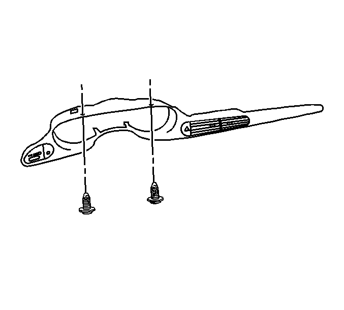
- Remove the two screws that attach the IP cluster bezel to the IP.
- Using a small flat-blade screwdriver, gently pry out and remove the IP cluster trim plate from the IP.
- Disconnect the electrical connectors from the other switches in the trim plate.
- Disconnect the electrical connector from the hazard warning switch.
- Using a small flat-blade screwdriver, carefully push in on the tabs to release the hazard warning switch from the IP cluster trim plate.
- Remove the hazard warning switch by pushing in an outward motion on the switch while holding onto the IP cluster trim plate.
- Install the new hazard warning switch by pushing in an inward motion on the switch while holding onto the IP cluster trim plate. Push inward on the switch until it is fully seated into the IP cluster trim plate.
- Connect the electrical connector to the hazard warning switch.
- Connect the electrical connectors to the other switches in the trim plate.
- Position and align the IP cluster trim plate to the IP and carefully press into place.
- Install the two screws that attach the IP cluster bezel to the IP.
- Install the upper steering column cover to the steering column.
- Position the lower steering column cover to the upper cover and install the three attaching screws.
- Install the AIR BAG fuse in the panel and install the cover.
- Turn the ignition switch to the ON position and verify that the AIR BAG light flashes seven times and goes out. Verify hazard warning switch operation.
Tighten
Tighten to 2 N·m (18 lb in).
Tighten
Tighten to 2 N·m (18 lb in).
Alero, Cutlass
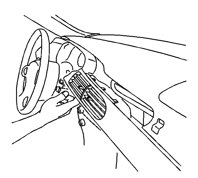
- Remove the hazard warning switch bezel from the IP using a small flat-bladed tool to release the retainers.
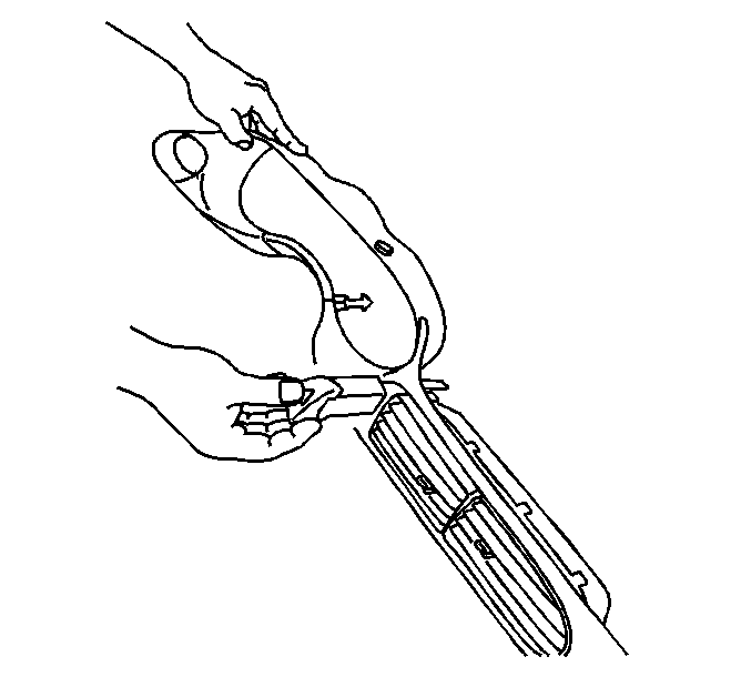
- Using two flat-blade screwdrivers (2), carefully release the two retainers that attach the IP center air outlet (1). With both retainers released, pull the bottom of the outlet rearward to release the top.
- Remove the two 7 mm hex head screws attaching the IP cluster trim panel to the IP.
- Remove the trim plate from the IP by pulling up and out to release the lower retainers.
- Disconnect the trip reset switch electrical connector.
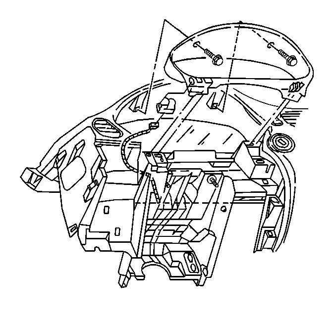
- Remove the four 7 mm hex head screws attaching the instrument cluster to the IP.
- Remove the instrument cluster from the opening and reposition as necessary. It is not necessary to disconnect the electrical connector.
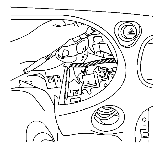
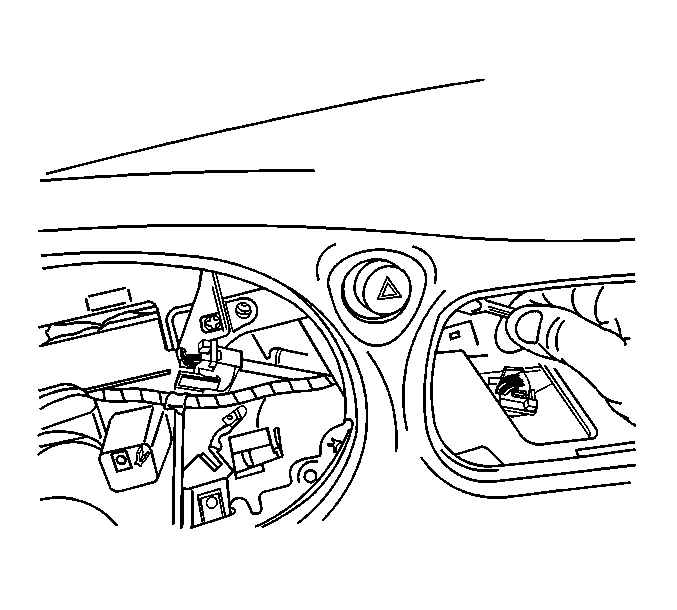
- Through the instrument cluster opening in the IP, remove one of the three 7 mm hex head screws that attach the hazard warning switch to the IP.
- Through the center air outlet opening in the IP, remove the remaining two 7 mm hex head screws that attach the hazard warning switch to the IP.
- Remove the hazard warning switch through the center air outlet opening.
- Disconnect the hazard warning switch electrical connector.
- Using a small flat-blade screwdriver, carefully release the two retaining features on the mounting bracket and remove the hazard warning switch from the bracket.
- Install the mounting bracket on the new hazard warning switch.
- Connect the electrical connector to the new hazard warning switch and insert it through the center air outlet opening in the IP.
- Position the switch and mounting bracket to the IP and install the two attaching screws through the center air outlet opening.
- Through the instrument cluster opening in the IP, install the remaining hazard warning switch attaching screw.
- Install the cluster in the IP. Install the four screws.
- Connect the electrical connector to the trip reset switch.
- Install the IP cluster trim panel to the IP and install the two screws.
- Install the center air outlet in the IP.
- Install the bezel on the hazard warning switch.
- Verify hazard warning switch operation.
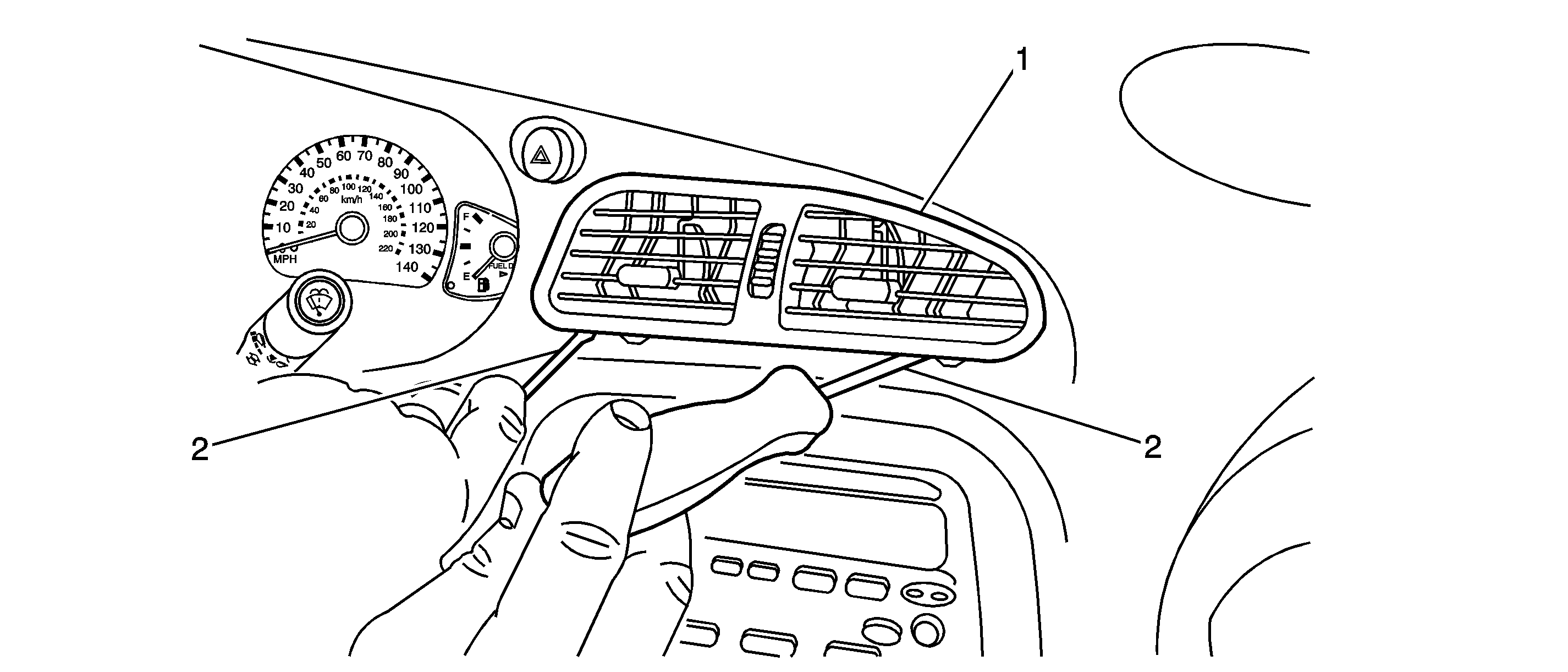
Important: Both retainers must be released at the same time in order to remove the air outlet in the next step.
Tighten
Tighten to 3 N·m (27 lb in).
Tighten
Tighten to 3 N·m (27 lb in).
Tighten
Tighten to 2 N·m (18 lb in).
Tighten
Tighten to 2 N·m (18 lb in).
Grand Am
- Apply the parking brake.
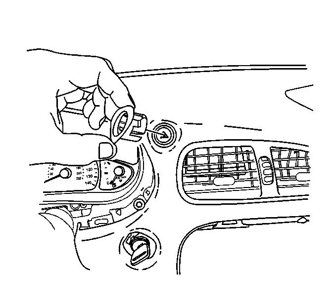
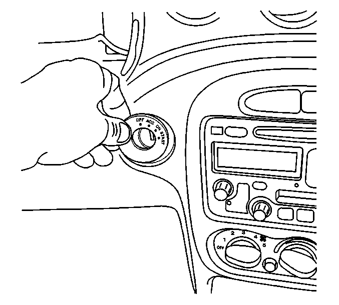
- Using a small flat-blade screwdriver, carefully remove the ignition switch bezel.
- Insert the key and turn the ignition switch to the ON position.
- Place the gearshift lever in the LOW position.
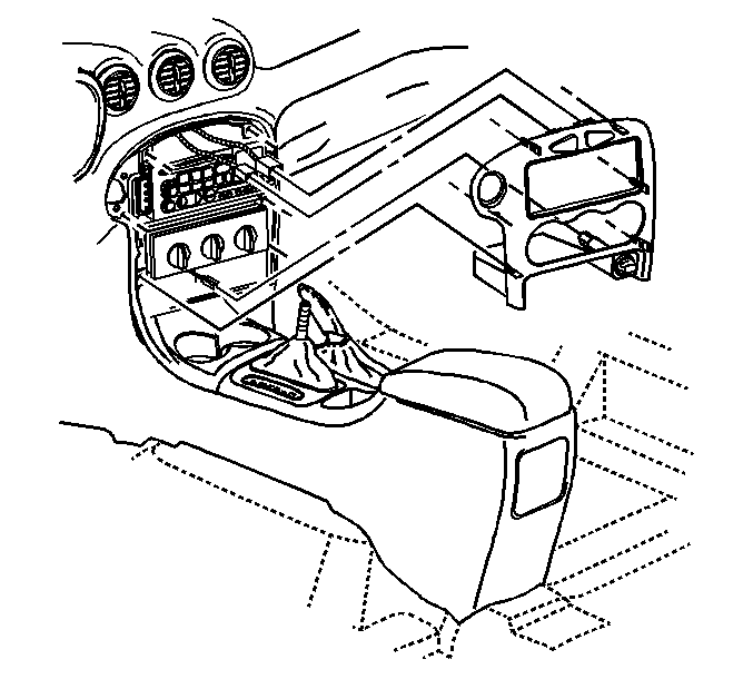
- Using a small flat-blade screwdriver, carefully disengage the accessory trim plate from the instrument panel (IP).
- Disconnect the electrical connectors from the switches installed in the accessory trim plate.
- Remove the three 7 mm hex head screws attaching the hazard warning switch mounting bracket to the accessory trim plate and remove the switch and bracket assembly.
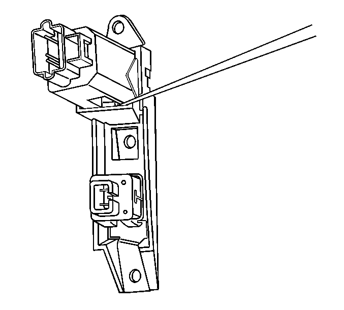
- Using a small flat-blade screwdriver, carefully depress the two retaining features on the side of the switch and remove the hazard warning switch from the bracket.
- Install the new hazard warning switch in the mounting bracket.
- Position the hazard warning switch and bracket assembly to the accessory trim plate and install the three attaching screws.
- Connect the electrical connectors to the switches in the accessory trim plate.
- Install the accessory trim plate to the IP and press into place until fully seated.
- Place the gearshift lever in the PARK position.
- Turn the ignition key to the OFF position and remove the key.
- Install the ignition switch bezel to the IP and press into place until fully seated.
- Verify hazard warning switch operation.
Tighten
Tighten to 3 N·m (27 lb in).
Claim Information
For vehicles repaired under the terms of this special policy, submit a claim with the information indicated below:
Repair Performed | Part Count | Part No. | Parts Allow | CC-FC | Labor Op | Labor Hours | Net Item |
|---|---|---|---|---|---|---|---|
Replace hazard warning switch | 1 | -- | * | MK-95 | T5609 |
| N/A |
Malibu | 0.4 | ||||||
Alero, Cutlass | 0.5 | ||||||
Grand Am | 0.3 | ||||||
Reimbursement for Previous Repairs (Canadian & Export Dealers/U.S. CAC) | N/A | N/A | N/A | MK-95 | T5610 | 0.2 | ** |
* -- The "Parts Allowance" should be the sum total of the current GMSPO Dealer Net price plus applicable Mark-Up or Landed Cost Mark-up (for Export) for the hazard warning switch needed to complete the repair. ** -- The amount identified in the "Net Item" column should represent the customer reimbursement amount. | |||||||
Customer Reimbursement -- For US
All customer requests for reimbursement for previous repairs for the special policy condition will be handled by the Customer Assistance Center, not by dealers.
A General Motors Special Policy Customer Reimbursement Procedure Form is included with the customer letter.
Important: Refer to the GM Service Policies and Procedures Manual, section 6.1.12 for specific procedures regarding customer reimbursement and the form.
Customer Reimbursement -- For Canada and Export
Customer requests for reimbursement of previously paid repairs for the special policy condition are to be submitted prior to or by January 31, 2006 for 1999-2000 vehicles and May 31, 2007 for 2001-2002 vehicles. Repairs must have occurred within 10 years of the date the vehicle was originally placed in service, or 150,000 km (240,000 km), whichever occurs first.
When a customer requests reimbursement, they must provide the following:
| • | Proof of ownership at time of repair. |
| • | Original paid receipt confirming the amount of unreimbursed repair expense(s) (including Service Contract deductible), a description of the repair, and the person or entity performing the repair. |
If the work was done by someone other than a GM dealership, the amount of reimbursement will be limited to the amount that the repair would have cost GM to have it completed by a GM dealership.
Dear General Motors Customer:
As the owner of a 1999-2002 model year Chevrolet Malibu, Oldsmobile Alero, Pontiac Grand Am or 1999 model year Oldsmobile Cutlass, your satisfaction with our product is very important to us.
This letter is intended to make you aware that some 1999-2002 model year Chevrolet Malibu, Oldsmobile Alero, Pontiac Grand Am, or 1999 model year Oldsmobile Cutlass vehicles may have a condition where the turn signal/hazard warning flashers become inoperative.
This is not a recall. Do not take your vehicle to your GM dealer as a result of this letter unless you believe that your vehicle has the condition as described above.
What We Have Done
General Motors is providing owners with additional protection for the turn signal/hazard warning flashers. If this condition occurs on your 1999-2000 model year Chevrolet Malibu, Oldsmobile Alero, Pontiac Grand Am or 1999 Oldsmobile Cutlass within 10 years of the date your vehicle was originally placed in service or 150,000 miles (240,000 km), whichever occurs first, the condition will be repaired for you at no charge .
What You Should Do
Repairs and adjustments qualifying under this special coverage must be performed by a General Motors dealer. You may want to call the service department at your dealer to find out how long they will need to have your vehicle so that you may schedule the appointment at a time that is a convenient time for you. This will also allow your dealer to order parts if they are not already in stock. Keep this letter with your other important glovebox literature for future reference.
Reimbursement
The enclosed form explains what reimbursement is available and how to request reimbursement if you have paid for repair for the special policy condition.
If you have any questions or need any assistance, must contact your dealer or the appropriate Customer Assistance Center at the number listed below. The Customer Assistance Center's hours of operation are from 8:00 AM to 11:00 PM, EST, Monday through Friday.
Division | Number | Text Telephones (TTY) |
|---|---|---|
Chevrolet | 1-800-630-2438 | 1-800-833-2438 |
Pontiac | 1-800-620-7668 | 1-800-833-7668 |
Oldsmobile | 1-800-630-6537 | 1-800-833-6537 |
Puerto Rico - Español | 1-800-496-9993 |
|
Virgin Islands | 1-800-496-9994 |
|
Guam | 1-671-648-8650 |
|
We are sorry for any inconvenience you may experience; however we have taken this action in the interest of your continued satisfaction with our products.
General Motors Corporation
Enclosure
04098
