SERVICE MANUAL UPDATE SEC.3-10 W/41 OPTION 2.3L ENGINE

SUBJECT: W-41 OPTION INFORMATION
MODELS/YEARS: 1992 OLDSMOBILE ACHIEVA SCX COUPE WITH 2.3L (VIN A) ENGINE
The following is service information, listed by service manual section concerning the 1992 W-41 package.
SECTION 3
Trim Height: There are no changes in the limits of the trim height specifications.
SECTION 3A
Alignment Specifications: There are no changes in the alignment specifications.
SECTION 3B
Restrictive Power Steering Gear: Limits the steering gear lock to lock travel. Service procedures will not be affected.
SECTION 3C
Front Coil Spring Rates: The coil spring rate will be increased from 20 N per mm to 24 N per mm. Service will not be affected.
The front stabilizer shaft has an increase in diameter from 21.5 mm (0.84 in.) to 30 mm (1.18 in.). Service procedures will not be affected.
SECTION 3D
Rear Coil Spring Rates: Variable rate, 28 to 47 N per mm. Service procedures will not be affected.
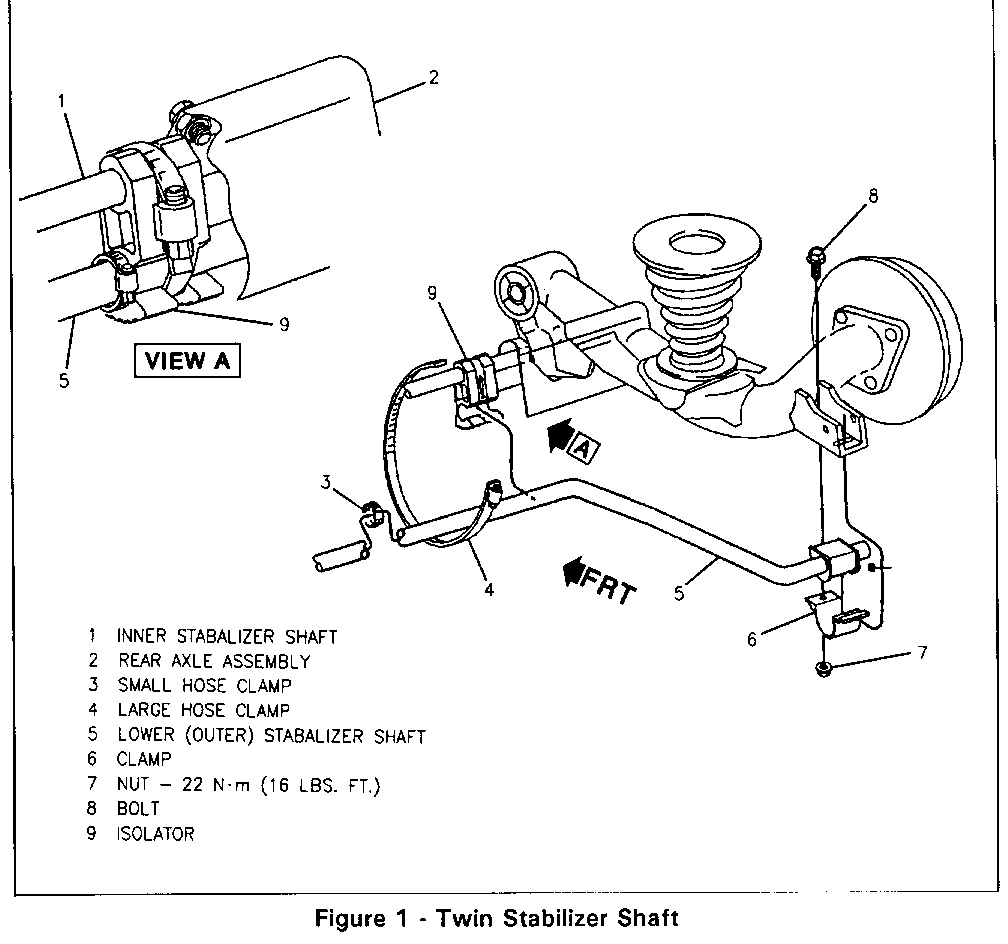
Rear Stabilizer Shaft: A second lower stabilizer shaft has been added, in addition to the one used in FE3 suspension.
Stabilizer Shaft - Lower (Outer) See Figure 1
Remove or Disconnect
1. Raise vehicle and support body with jack stands. Refer to Section OA.
2. Insulator nuts and isolator clamps.
3. Lower Stabilizer Shaft.
Install or Connect
1. Lower Stabilizer shaft.
2. Insulator nuts and isolator clamps. Tighten insulator nuts to 22 N.m (16 lbs. ft.) and insulator clamps to 3.75 N.m (33 lbs. in.).
3. Lower vehicle.
Stabilizer Shaft - Upper (Inner) See Figure 1
Remove or Disconnect
1. Raise vehicle and support body with jack stands. Refer to Section OA.
2. Lower stabilizer shaft. Refer to Stabilizer Shaft - Lower, in this bulletin.
3. Nuts and bolts.
4. Upper stabilizer shaft.
Install or Connect
1. Upper stabilizer shaft.
2. Nuts and bolts and tighten nuts to 22N.m (16lbs.ft.).
3. Lower stabilizer shaft. Refer to Stabilizer Shaft-Lower, in this bulletin.
4. Lower vehicle.
SECTION 3G
CCR Harness Modifications: Covered in 1992 Achieva Service Manual.
SECTION 5
Brake Pipe Hose and Cable Routing: Will not change.
SECTION 6A7
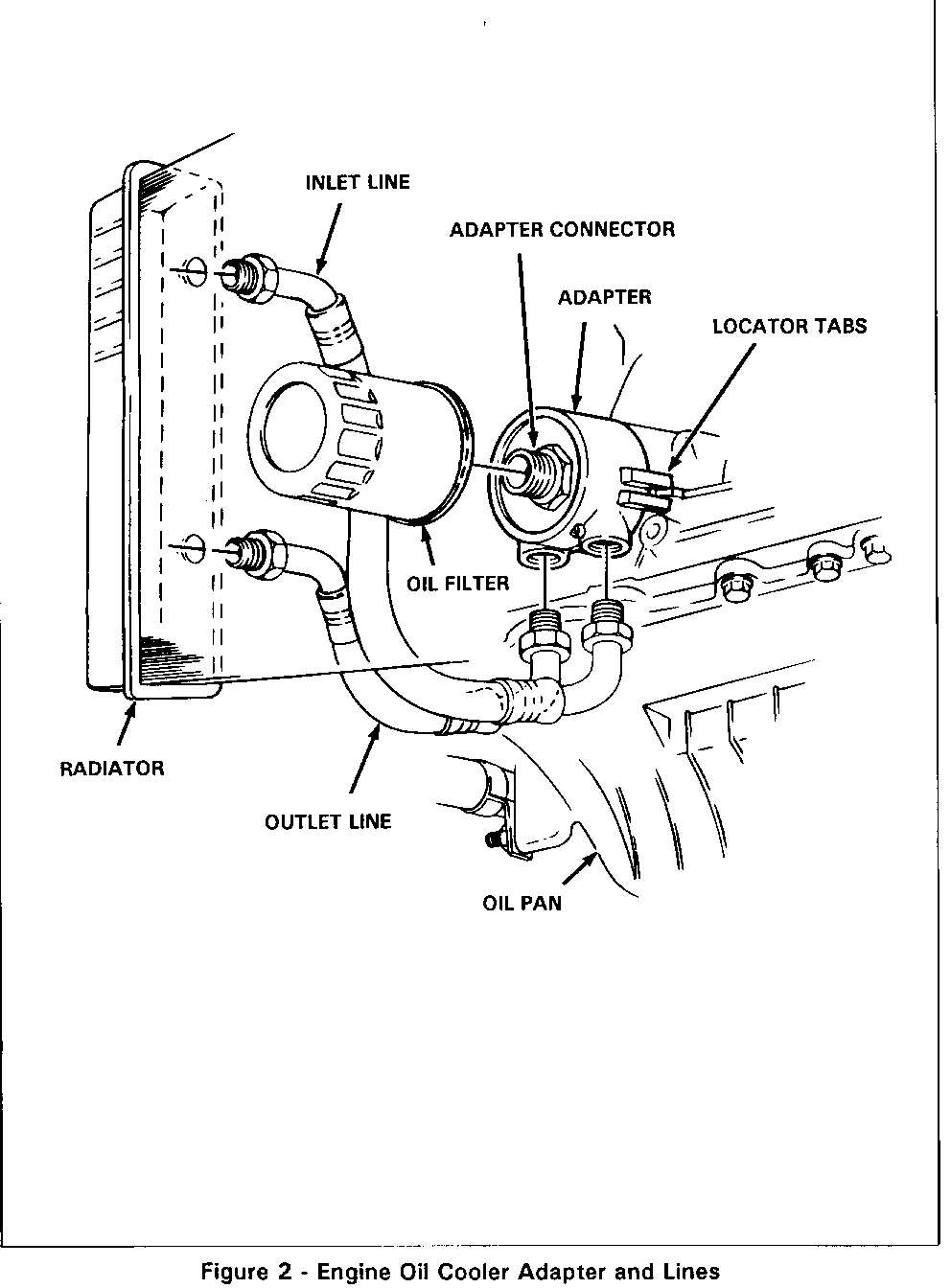
The Engine Oil Cooler is available on W41 vehicles with the C41 (Heater only) option. See Figure 2.
Engine Oil Cooler Adapter
Remove or Disconnect
1. Raise vehicle.
2. Disconnect cooler lines from adapter.
3. Remove oil filter.
4. Remove connector, adapter and "O" ring. Inspect "O" ring seal, replace if damaged or deformed.
Install or Connect
1. Install "O" ring, adapter and connector.
2. Install oil filter.
3. Connect cooler lines to adapter.
4. Lower vehicle.
5. Inspect oil level, add oil as necessary.
6. Start engine and check for oil leaks.
Engine 0.1 Cooler Inlet Line ---------------------------- Remove or Disconnect -------------------- 1. Disconnect inlet line from radiator.
2. Raise vehicle.
3. Remove inlet line from adapter.
Install or Connect
1. Install inlet line to adapter.
2. Lower vehicle.
3. Connect inlet line to radiator.
4. Inspect oil level, add oil as necessary.
5. Start engine and check for oil leaks.
Engine Oil Cooler
Remove or Disconnect
1. Raise vehicle.
2. Disconnect right engine splash shield.
3. Remove outlet line from radiator and adapter.
Install or Connect
1. Install outlet line to radiator and adapter.
2. Install right engine splash shield.
3. Lower vehicle.
4. Inspect oil level, add oil as necessary.
5. Start engine and check for oil leaks.
Camshaft
The W41 camshaft has a new profile. There is no affect on service procedures.
Power Steering Belt and Drive Pulley
The W41 P/S pump drive pulley is smaller in diameter. No P/S pump drive pulley service parts are available. If the drive pulley needs to be replaced, replace both the belt and the drive pulley with normal size parts.
SECTION 6C
Fuel Tank: Has a deeper sump on C41 vehicles only. Service will not be affected.
SECTION 6F
Exhaust System: Lower back pressure muffler. Internal change only. Service will not be affected.
SECTION 7C
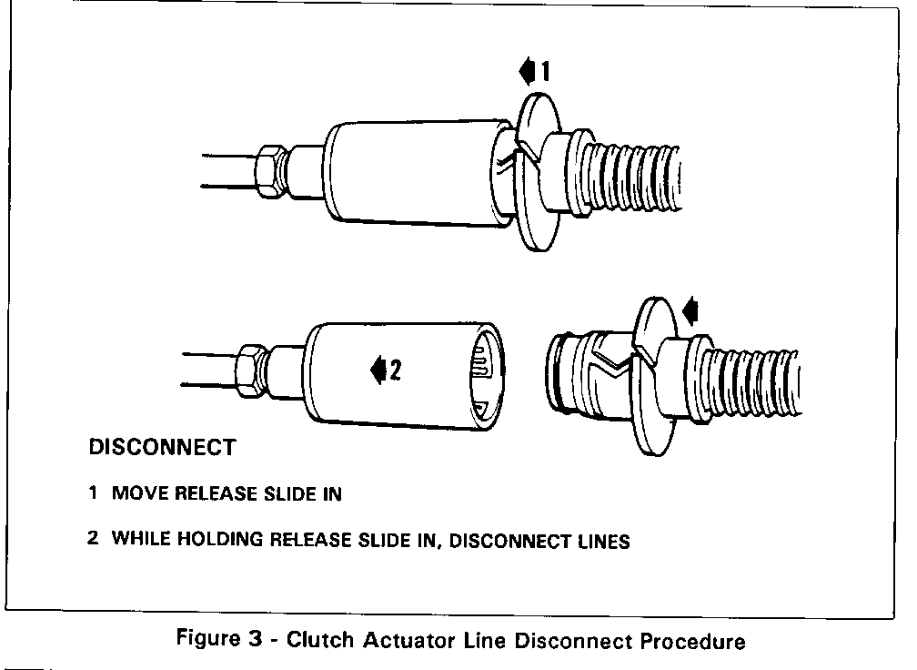
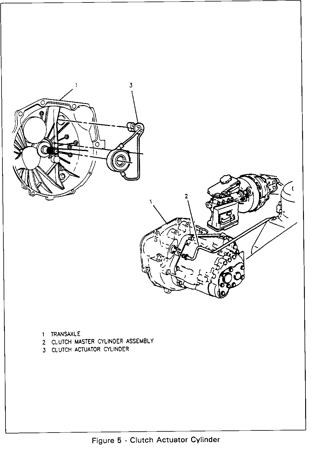
The Clutch Actuator Cylinder combines the release bearing and the actuator cylinder. Refer to Figures 3 through 5. To replace the clutch actuator cylinder, the transaxle will need to be removed.
Clutch Actuator Cylinder
Remove or Disconnect
1. Battery.
2. Left I/P sound insulator and disconnect clutch pushrod from pedal.
3. Air cleaner assembly and duct to throttle body.
4. Power steering pump bracket.
5. Transaxle shift cables from transaxle.
6. Hydraulic line from the clutch actuator cylinder. Refer to Figure 3.
7. Vacuum line from transaxle.
8. Shift cable bracket.
9. Upper transaxle-to-engine bolts.
10. Install engine support fixture.
11. Upper transaxle mount and through bolt.
12. Raise vehicle.
13. Drain transaxle fluid.
14. Both front wheel and tire assemblies.
15. Left side inner splash shield.
16. Both front ABS wheel speed sensor connectors from sensor and suspension support.
17. Both ball joints from steering knuckle.
18. Both stabilizer link pins.
19. Right drive axle brace bolts.
20. Drive axles from transaxle.
21. Left side stabilizer shaft bushing nuts.
22. Heater pipe brace bolts.
23. Left suspension support and attaching bolts.
24. Flywheel inspection cover.
25. Lower transaxle mount and through bolt.
26. Ground connections.
27. Lower vehicle.
28. Lower engine and transaxle assembly.
29. VSS/backup light switch connector.
30. Raise vehicle.
31. Support transaxle with jack stand.
32. Remaining transaxle-to-engine bolts.
33. Transaxle by sliding it away from the engine and carefully lower the jack.
34. Remove clutch actuator cylinder. The rubber grommet will slide out of transaxle housings with clutch lines.
Important: Make sure no oil or grease contacts the clutch actuator cylinder or damage may occur.
Install or Connect
1. Clutch actuator cylinder.
2. Position the transaxle to the engine.
3. Lower transaxle to engine bolts. Tighten to specification.
4. Remove transaxle support jack.
5. Both transaxle mount with through bolts only.
6. VSS/backup light switch connectors.
7. Heater hose bolt.
8. Transaxle shift levers.
9. Lower vehicle.
10. Raise engine and transaxle assembly and align to mounts.
11. Raise vehicle.
12. Bolts for both transaxle mounts. Tighten to specification.
13. Both drive axles into transaxle.
14. Left suspension support and attaching bolts and nuts.
15. Left side stabilizer shaft bushing.
16. Right drive axle brace bolts.
17. Ball joints, nuts and cotter pins.
18. Left stabilizer link pins. Tighten to specification.
19. ABS connectors to sensor.
20. Left inner splash shield.
21. Flywheel inspection cover.
22. Left front wheel and tire assembly.
23. Lower vehicle.
24. Top rear transaxle mount to transaxle bolts.
25. Remove engine support fixture.
26. Upper transaxle to engine bolts. Tighten bolts to specifications.
27. Shift cable bracket.
28. Shift cables.
29. Vacuum lines.
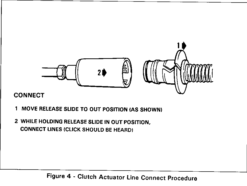
30. Hydraulic line to the clutch actuator cylinder. Refer to Figure 4.
31. Power steering pump bracket. Adjust the belt.
32. Air cleaner assembly and bracket.
33. Battery.
34. Clutch pushrod to clutch pedal.
35. Left I/P sound insulator.
36. Fill transaxle.
SECTION 8C
Speedometer: Top speed indicator of 140 mph. Service procedures will not be affected.
SECTION 10
The W41 will not affect body service procedures. Refer to Section 10-1 of the 1992 Achieva Service Manual for General body service procedures.
Please note these changes in your copies of the 1992 Achieva car Service Manual.
General Motors bulletins are intended for use by professional technicians, not a "do-it-yourselfer". They are written to inform those technicians of conditions that may occur on some vehicles, or to provide information that could assist in the proper service of a vehicle. Properly trained technicians have the equipment, tools, safety instructions and know-how to do a job properly and safely. If a condition is described, do not assume that the bulletin applies to your vehicle, or that your vehicle will have that condition. See a General Motors dealer servicing your brand of General Motors vehicle for information on whether your vehicle may benefit from the information.
