Cylinder Head Assemble L98, LS2
Tools Required
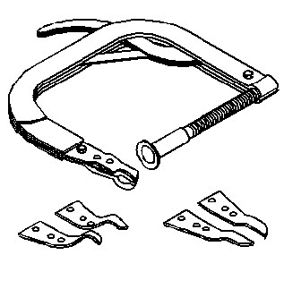
J 8062 Valve Spring Compressor - Head Off
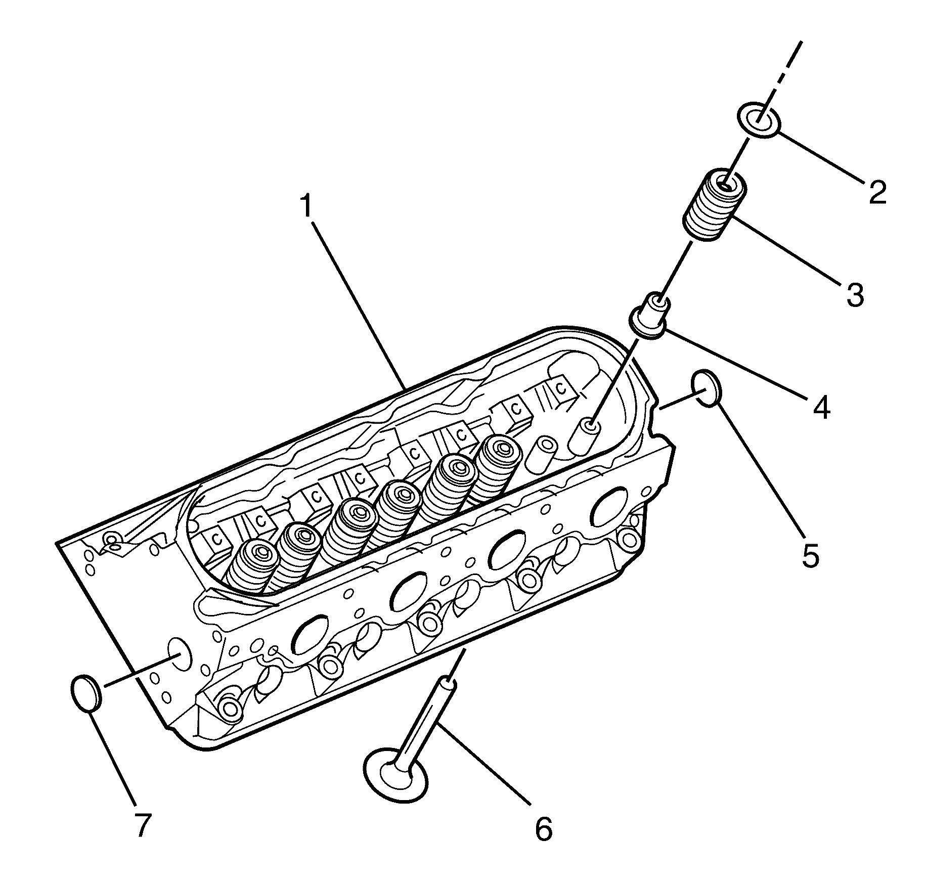
- Clean the cylinder head valve spring shim area.
- Apply threadlock, to the sides of the cylinder head core hole plugs (6) if removed.
- Install the core hole plugs (6) into the cylinder head if removed.
- Install the valve (5) into the correct port.
- Install the valve stem oil seal (4).
- Install the valve spring (3).
- Install the valve spring cap (2).
- Use a commercially available in order to compress the valve spring.
- Install the valve stem keys.
- Measure the valve spring installed height using a ruler.
- Install the remaining valves, springs, and other components.
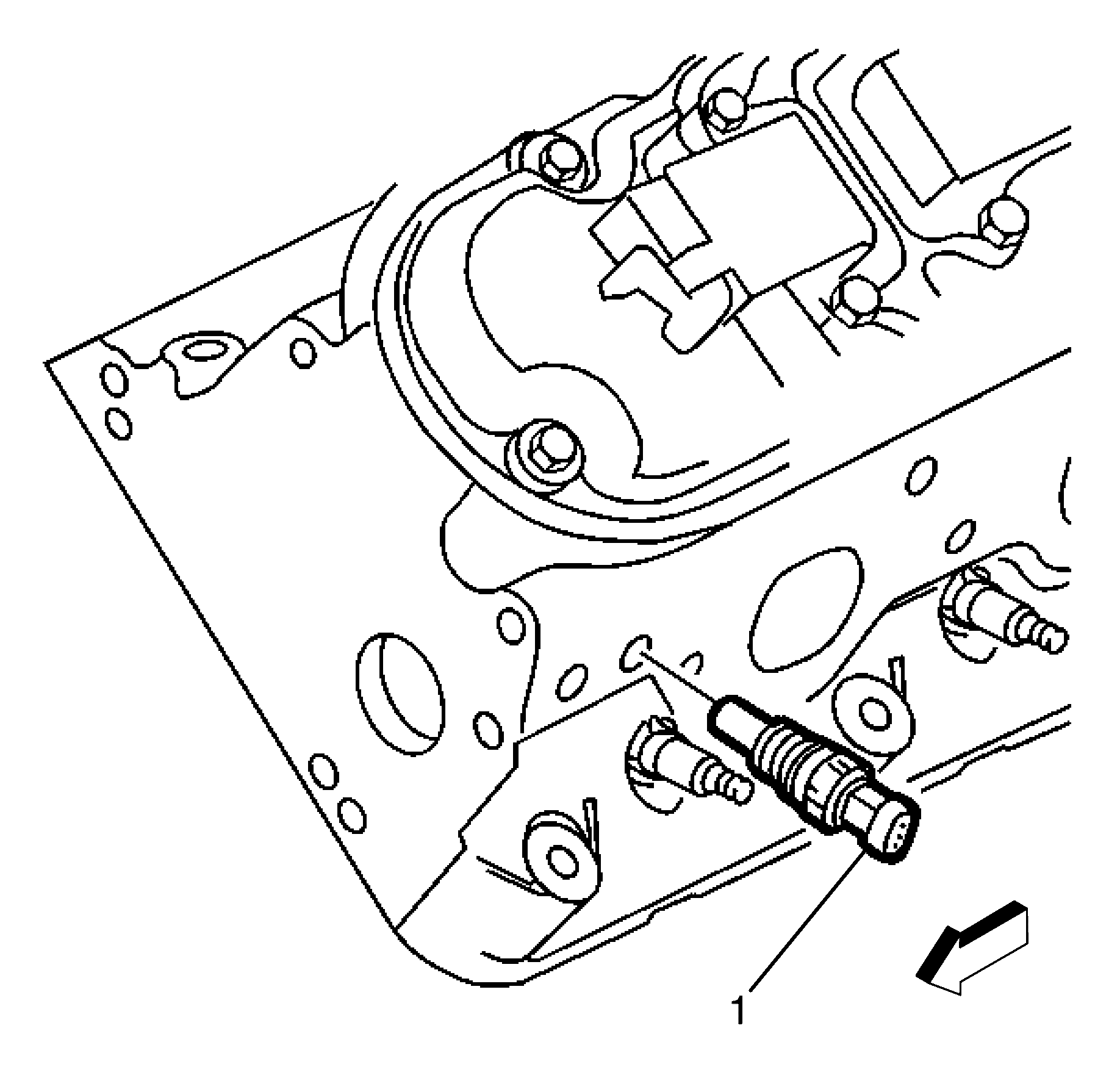
- Coat the Engine Coolant Temperature (ECT) sensor threads with sealer or the equivalent.
- Install the ECT sensor (1) to the cylinder head.
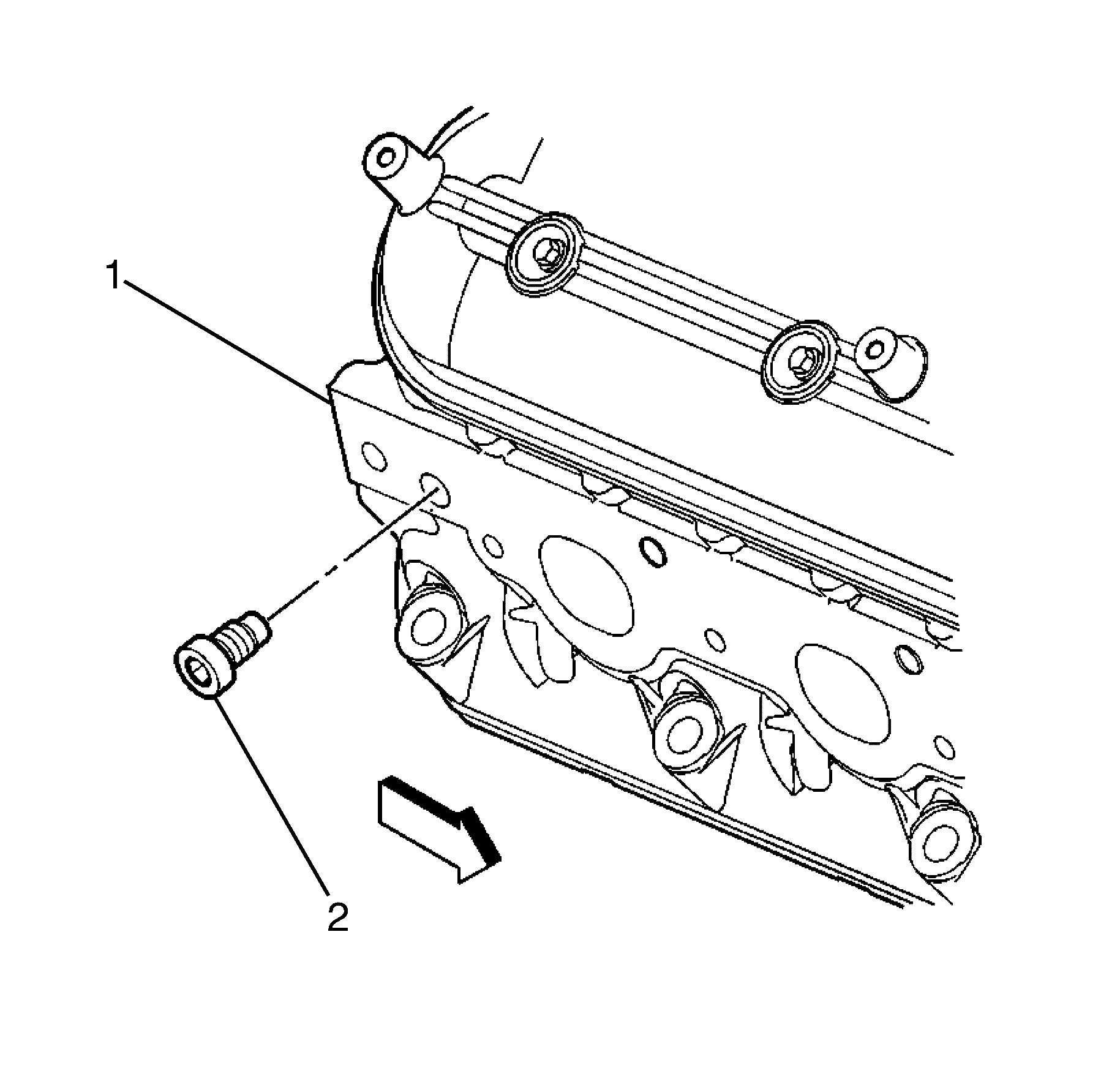
- Install sealant, to the threads of the coolant plug (2).
- Install the coolant plug (2) to the right cylinder head (1).
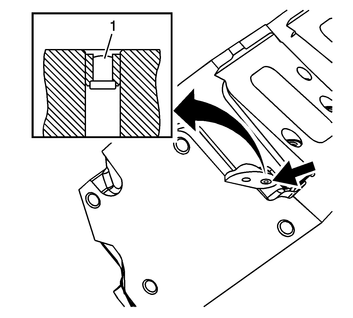
A correctly installed plug should be installed 2.5 mm (0.1 in) below the end face of the cylinder head (1).
Important: When using the valves and related components again, install the parts to their original location in the cylinder head (1).
Important: The valve stem oil seal alignment and position on the valve guide is critical. An incorrectly installed valve stem oil seal may lead to above acceptable oil consumption, increased vehicle emissions, or component damage.
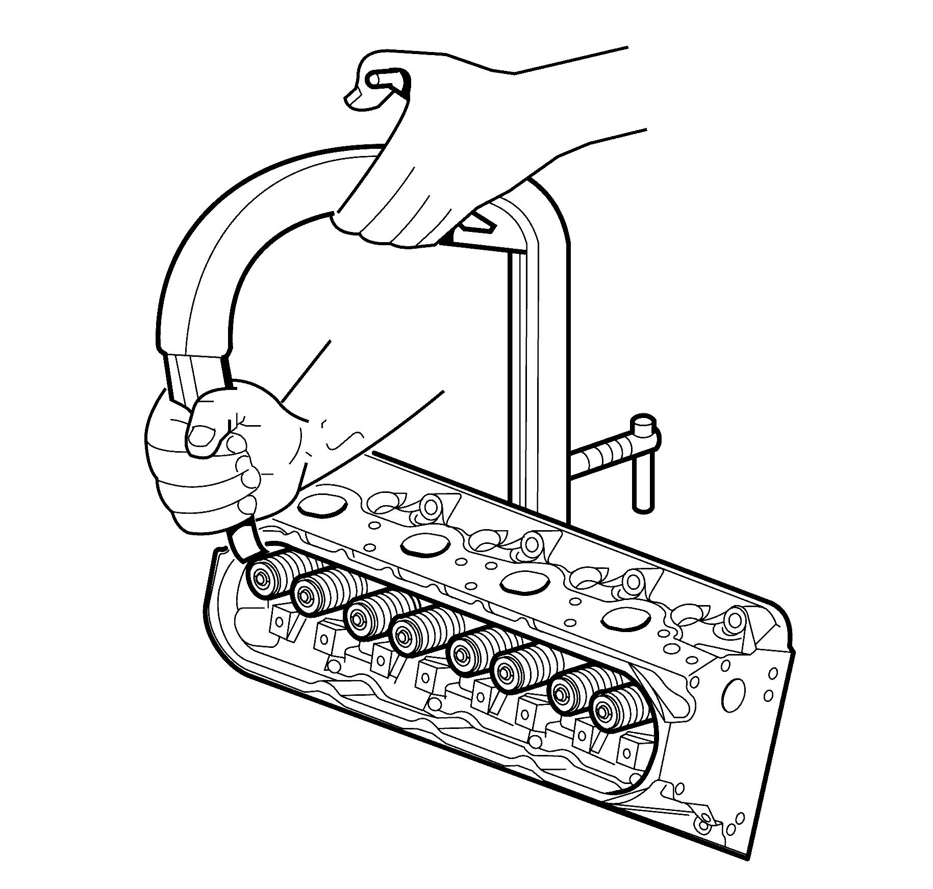
| 9.1. | Use grease to hold the keys in place and remove the J 8062 . |
| 9.2. | Ensure the keys seat correctly in the groove of the valve stem. |
| 9.3. | Tap the end to the valve stem with a plastic faced hammer to seat the keys, if necessary. |
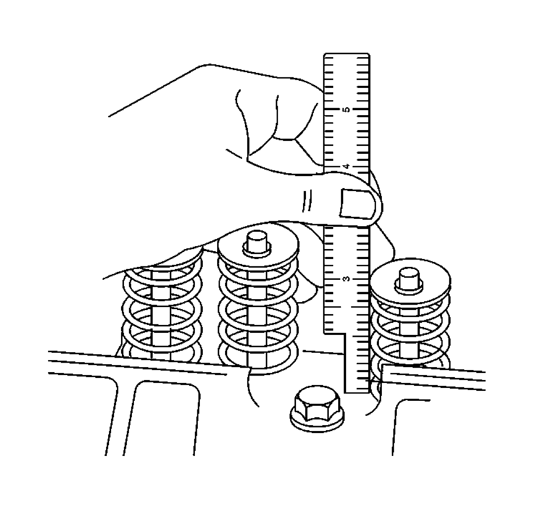
Measure from the base of the valve spring to the top of the valve spring.
Specification
| • | If the installed height exceeds 46.25 mm (1.82 in), install a valve spring shim of approximately 0.5 mm (0.02 in) thick. |
| • | DO NOT shim the valve spring to obtain less than the specified height. |
| DO NOT assemble the components without a spring shim on the cylinder head. |
Notice: Replacement components must be the correct part number for the application. Components requiring the use of the thread locking compound, lubricants, corrosion inhibitors, or sealants are identified in the service procedure. Some replacement components may come with these coatings already applied. Do not use these coatings on components unless specified. These coatings can affect the final torque, which may affect the operation of the component. Use the correct torque specification when installing components in order to avoid damage.
Notice: Use care when handling the coolant sensor. Damage to the coolant sensor will affect the operation of the fuel control system.
Notice: Refer to Fastener Notice in the Preface section.
Tighten
Tighten the ECT sensor to 20 N·m (15 lb ft).
Tighten
Tighten the plug to 20 N·m (15 lb ft).
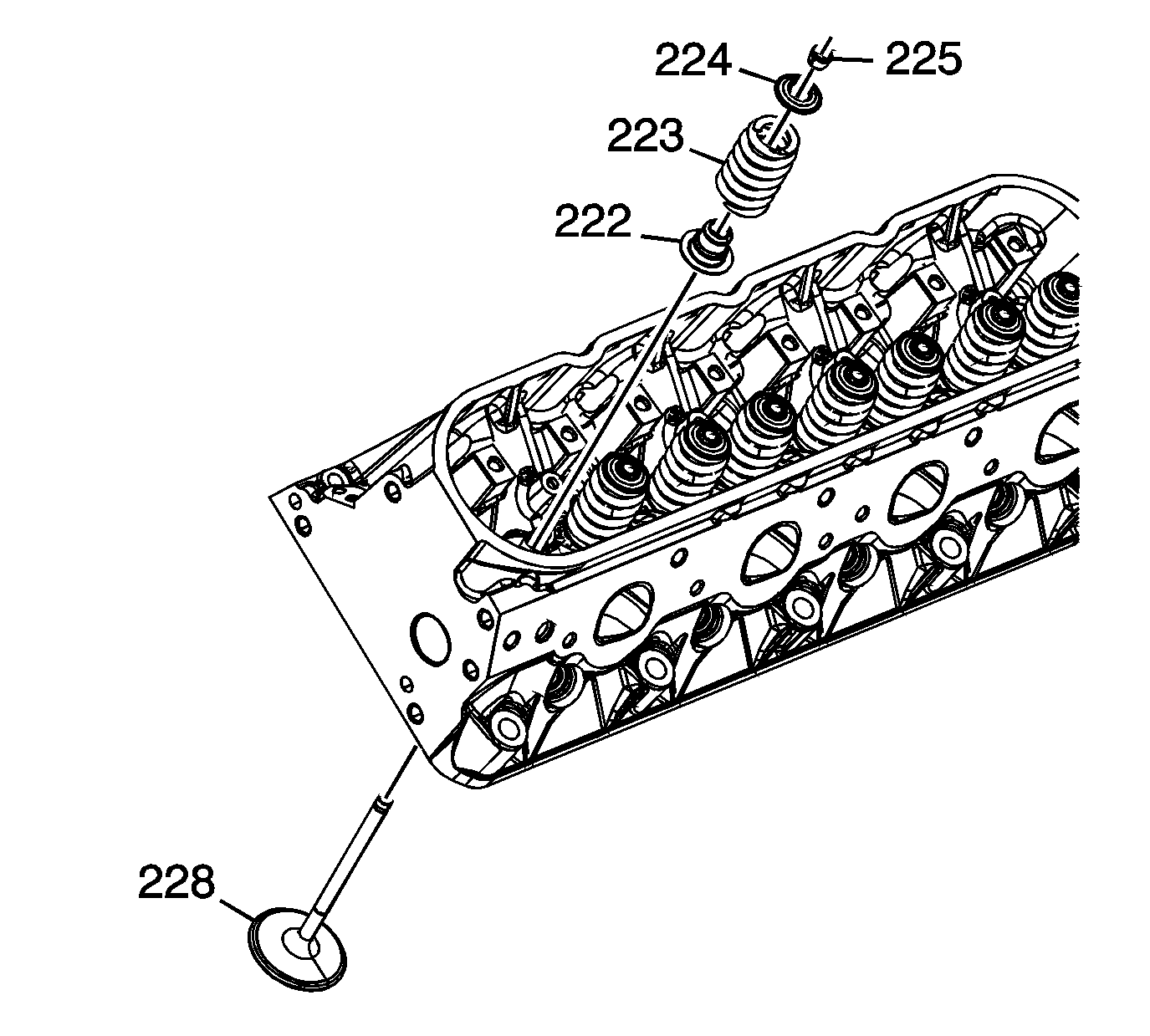
Cylinder Head Assemble LS3
Tools Required
J 8062 Valve Spring Compressor - Head Off
- Clean the cylinder head valve spring shim area.
- Install the valves (228) into the proper port. Refer to Separating Parts.
- Install the valve stem oil seal (222).
- Install the valve spring (223).
- Install the valve spring cap (224).
- Using the J 8062 , compress the valve spring.
- Install the valve stem keys.
- Using a ruler, measure the valve spring installed height.
- Install the remaining valves, springs, and other components.
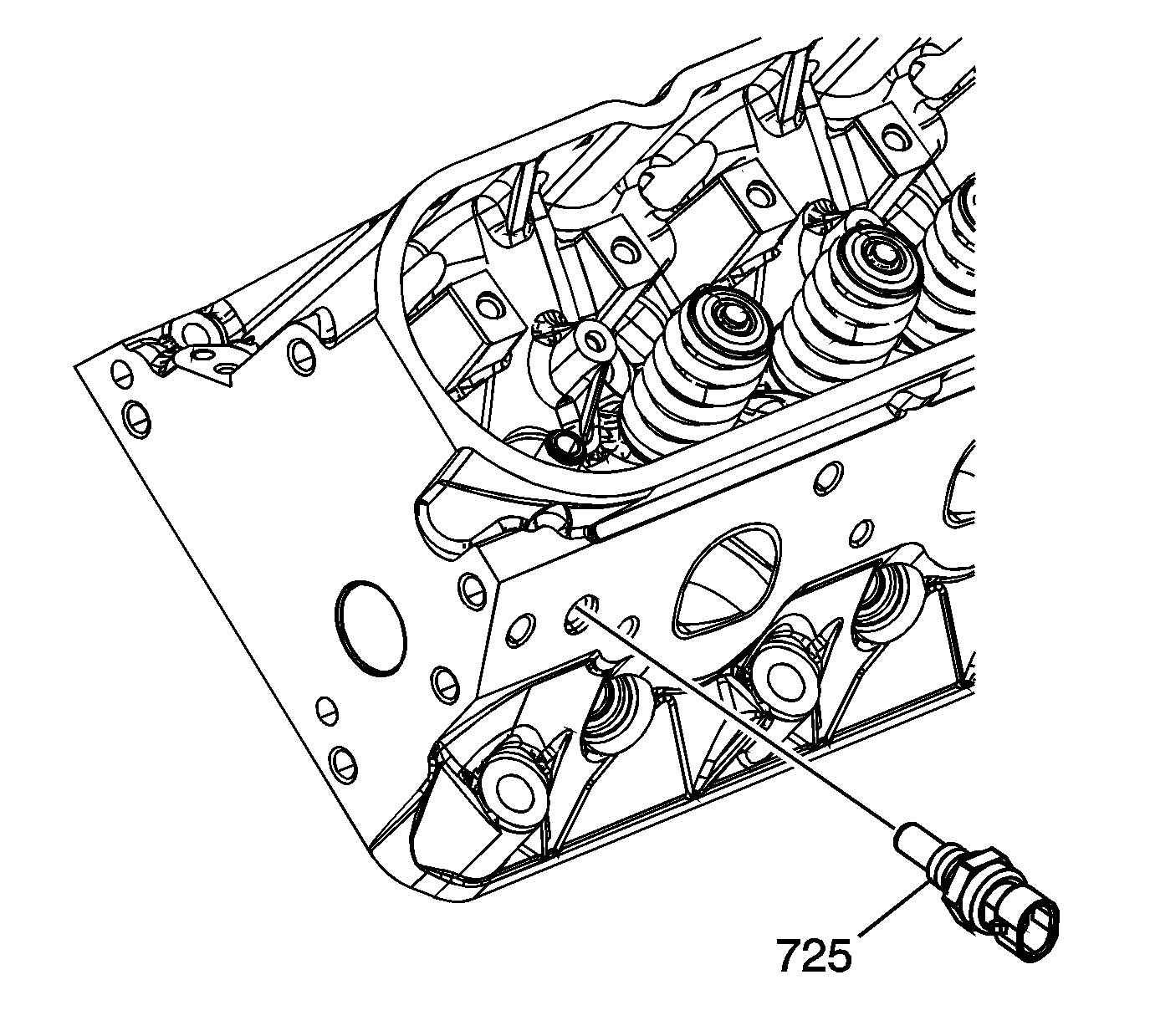
- Install sealant Loctite 565™, or equivalent, to the threads of the coolant temperature sensor (725).
- Install the coolant temperature sensor into the left cylinder head.
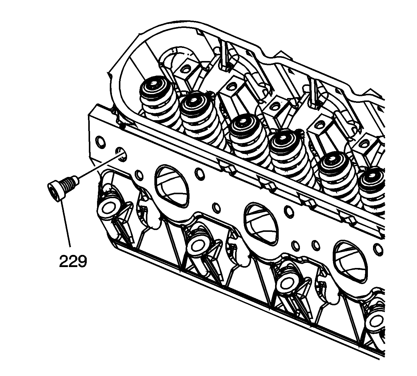
- Install sealant Loctite 565™, or equivalent, to the threads of the cylinder head plug (229).
- Install the cylinder head plug to the right cylinder head.
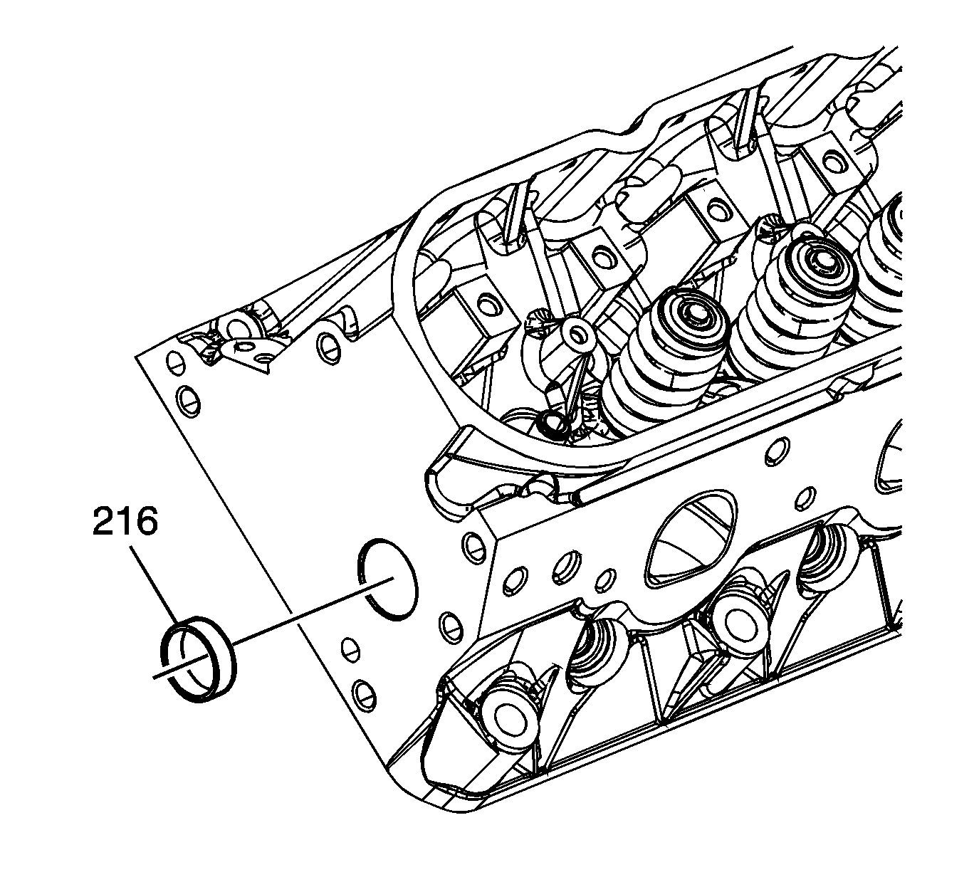
- Apply threadlock Loctite 242™, or equivalent, to the sides of the cylinder head plugs (216).
- Install the cylinder head plugs into the cylinder head.
- Second design applications use a rivet-type plug at the top rear coolant passage of each cylinder head. If service of a leaking plug is required, it is necessary to remove the cylinder head from the engine to properly remove the plug.
- If plug removal is required, install a first design coolant air bleed cover and bolt to complete the repair.
Important: When using the valves and related components again, install the parts to their original location.
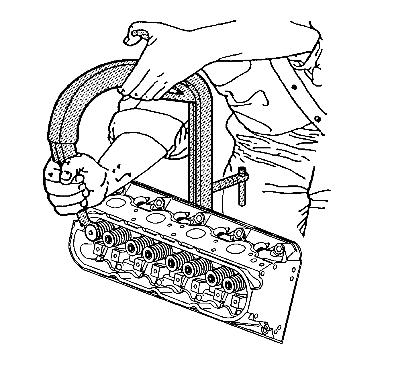
| 7.1. | Use grease in order to hold the keys in place and remove the J 8062 . |
| 7.2. | Ensure the keys seat properly in the groove of the valve stem. |
| 7.3. | Tap the end of the valve stem with a plastic face hammer to seat the keys, if necessary. |
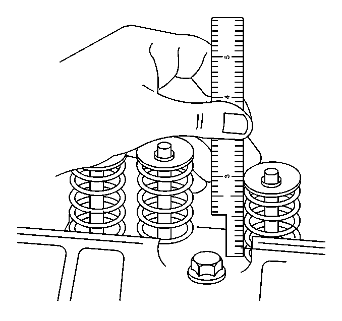
Measure from the base of the valve spring to the top of the valve spring.
Specification
| • | If the installed height exceeds 46.25 mm (1.82 in), install a valve spring shim of approximately 0.5 mm (0.02 in) thick. |
| • | Do not shim the valve spring to obtain less than the specified height. |
| Do not assemble the components without a spring shim on the cylinder head. |
Notice: Refer to Fastener Notice in the Preface section.
Tighten
Tighten the coolant temperature sensor to 20 N·m
(15 lb ft).
Tighten
Tighten the cylinder head plug to 20 N·m
(15 lb ft).
A properly installed plug should be installed 2.5 mm (0.1 in) below the end face of the head.