Fuel Tank Replacement LWB SWB
Removal Procedure
Tools Required
EN-48536 Frame Support Tool (Engine Lower 65 mm Kit)
- Raise and support the vehicle. Refer to Lifting and Jacking the Vehicle .
- Drain the fuel tank. Refer to Fuel Tank Draining .
- Relieve the fuel system pressure. Refer to Fuel Pressure Relief .
- Remove the exhaust system. Refer to Exhaust System Replacement .
- Remove the propeller shaft. Refer to Propeller Shaft Replacement .
- Remove the right rear wheel. Refer to Tire and Wheel Removal and Installation .
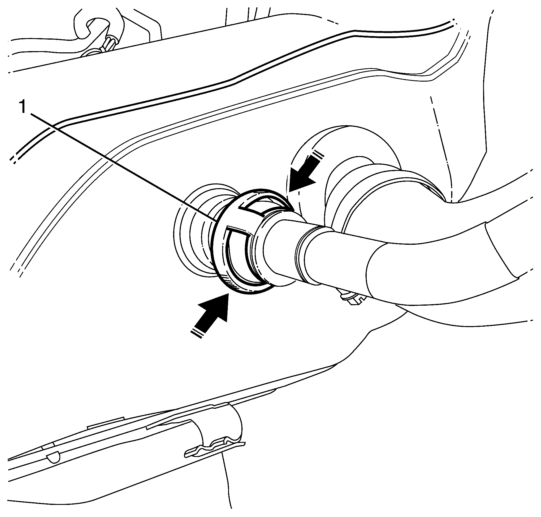
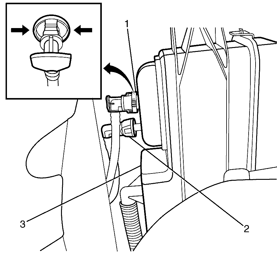
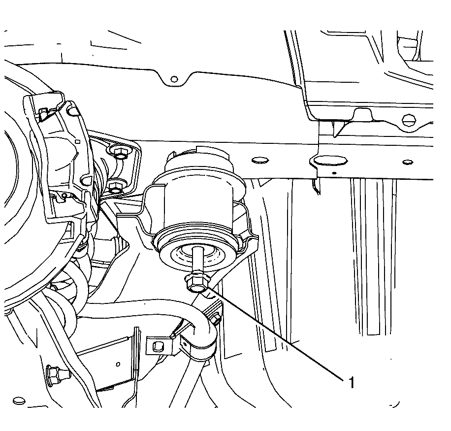
- Disconnect the evaporative emission (EVAP) line (1), by squeezing both sides of the line (as indicated in the illustration) and pulling it toward the rear of the vehicle.
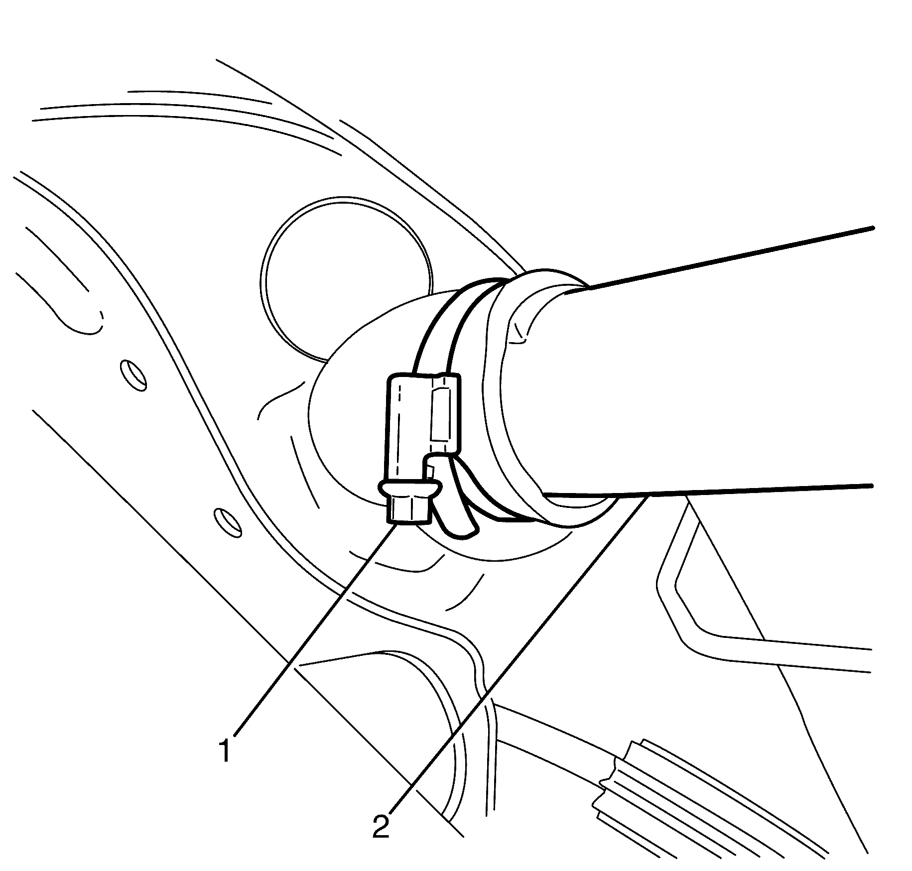
- Release the worm drive hose clamp (1) and remove the filler tube (2).
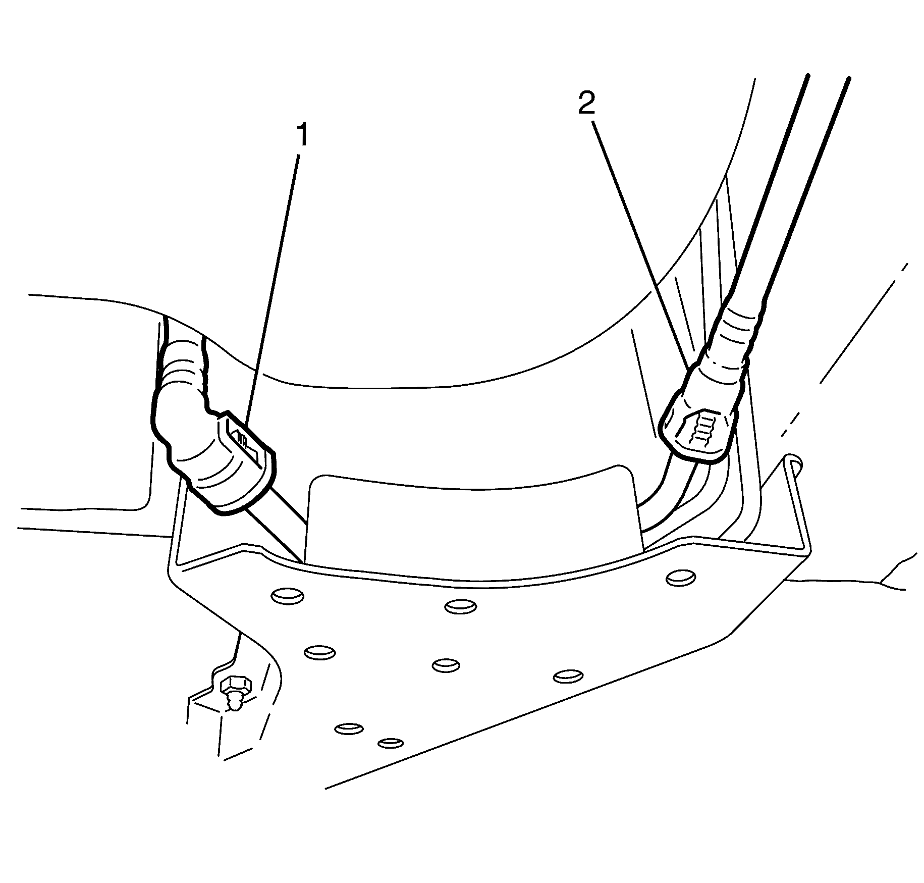
- Disconnect the fuel feed line (1) and evaporative emission (EVAP) line (2). Refer to Plastic Collar Quick Connect Fitting Service .
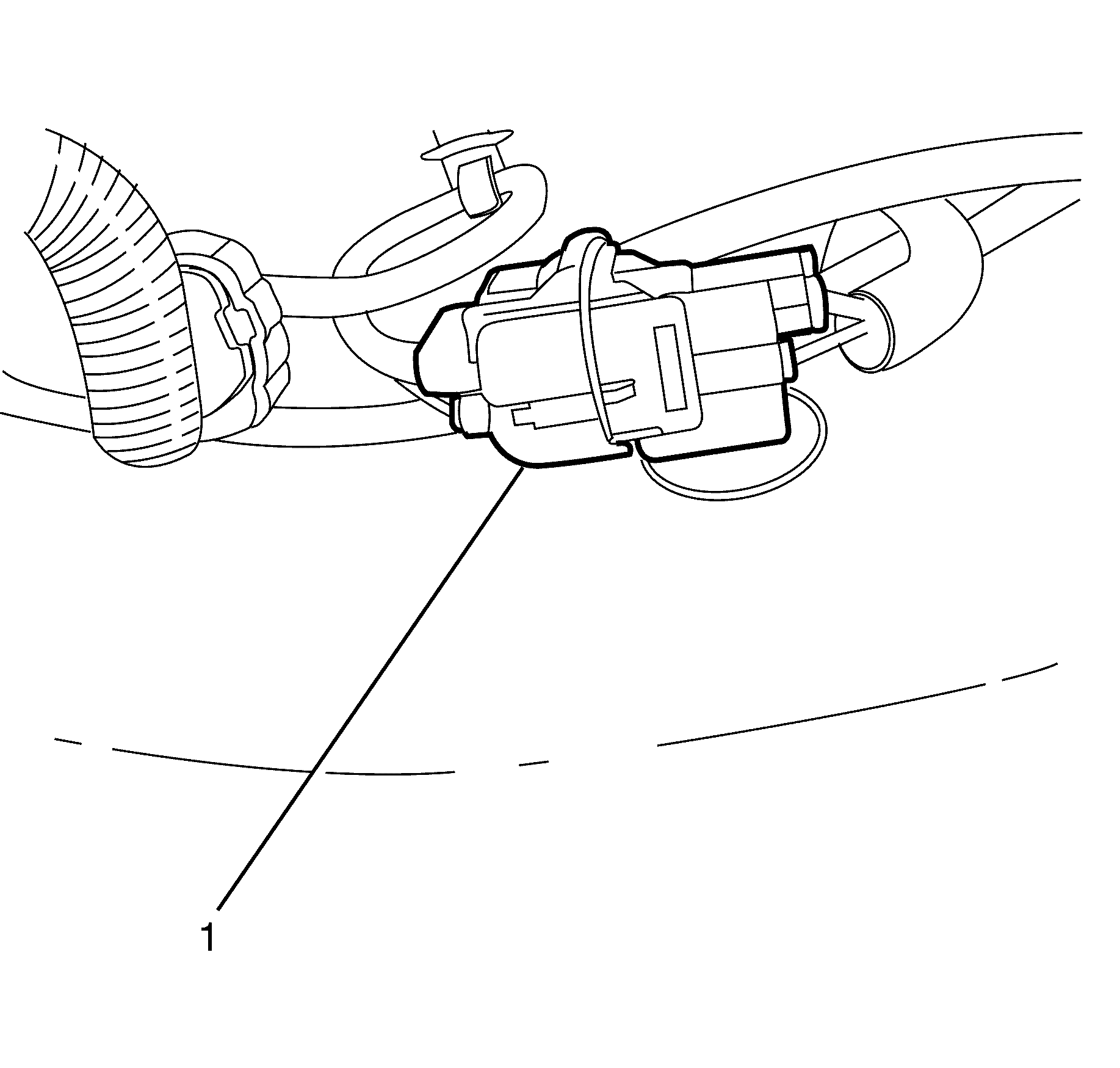
- Disconnect the fuel tank electrical connector (1).
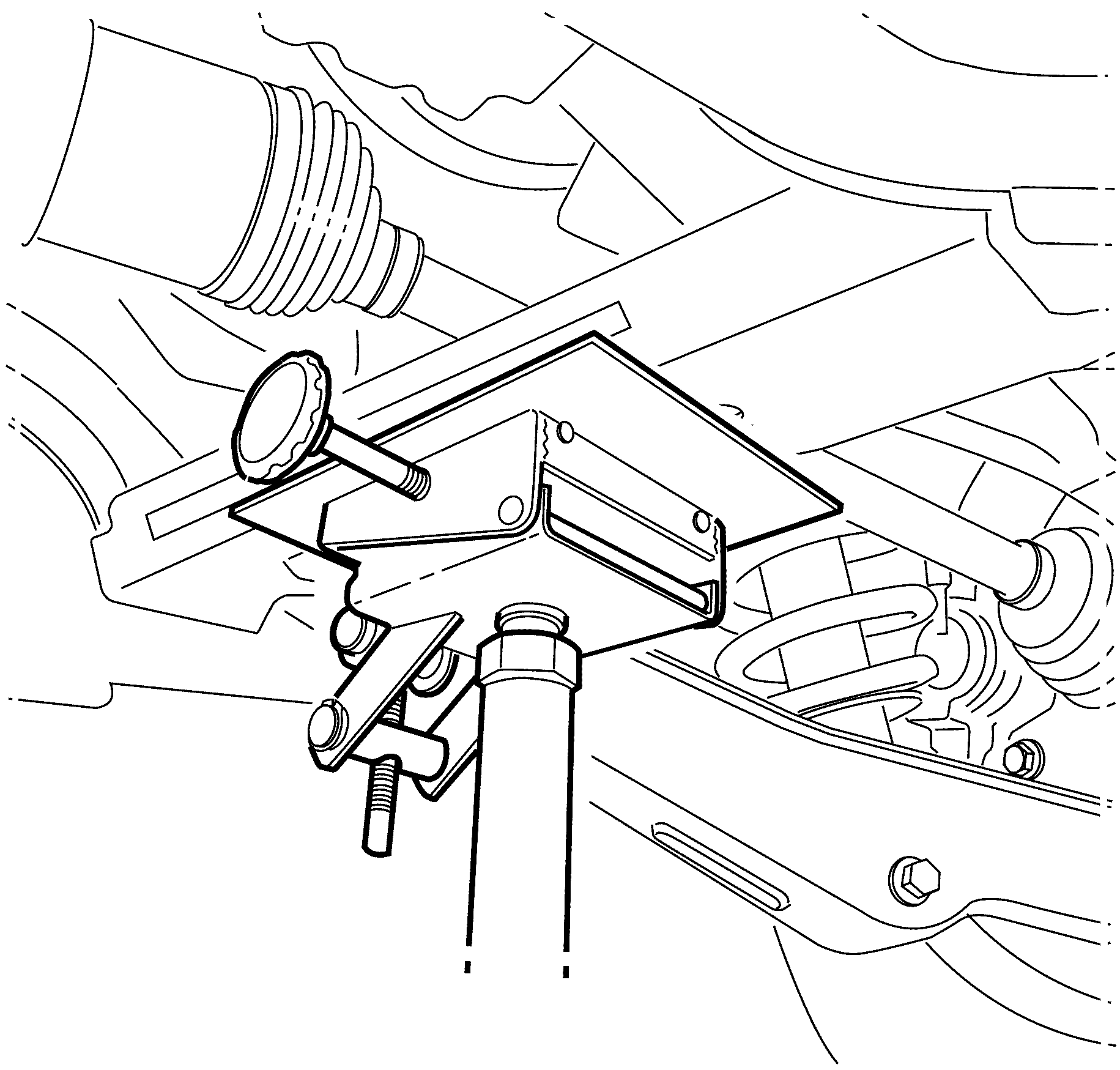
- Support the rear frame assembly using a suitable tool.
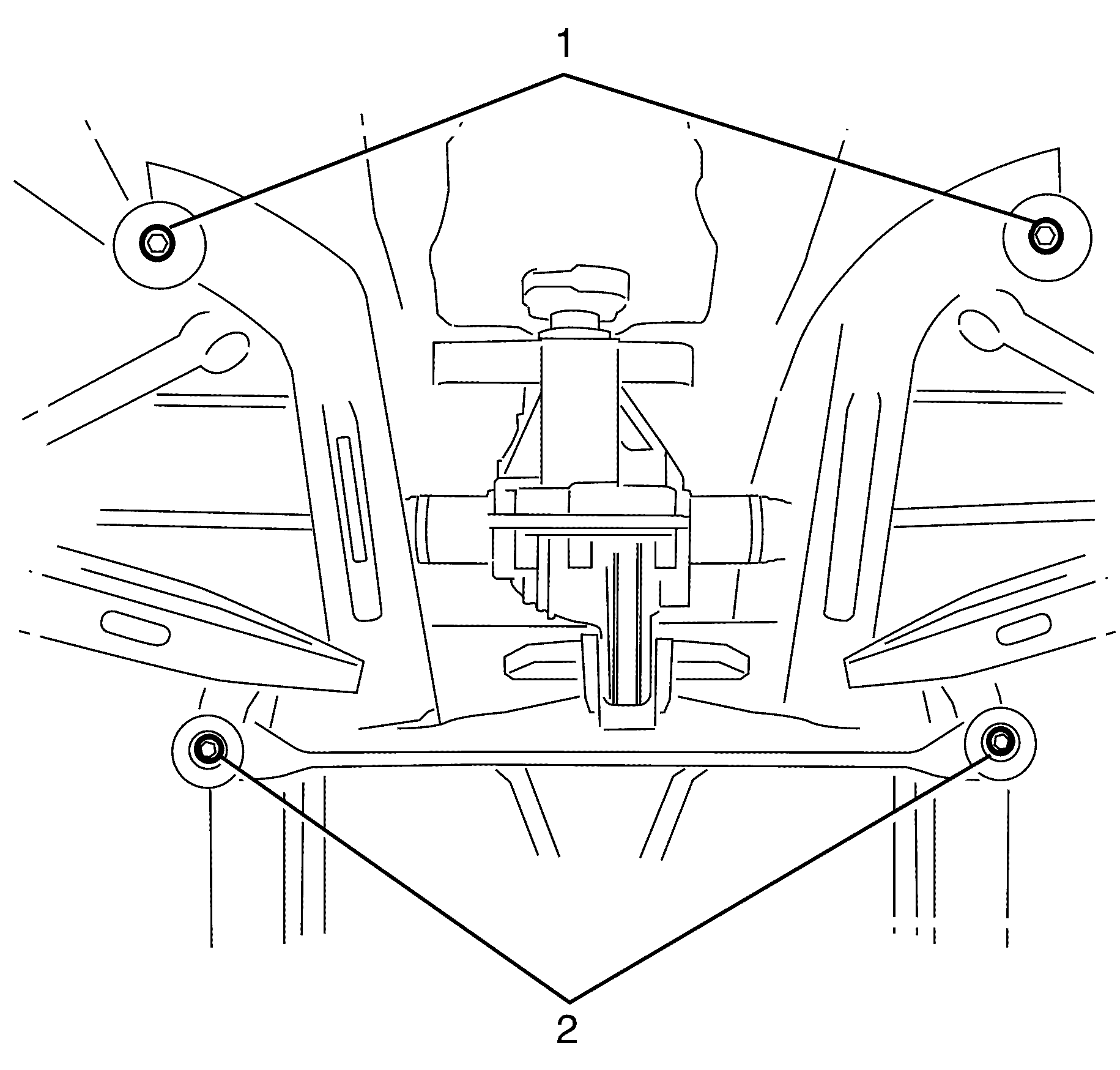
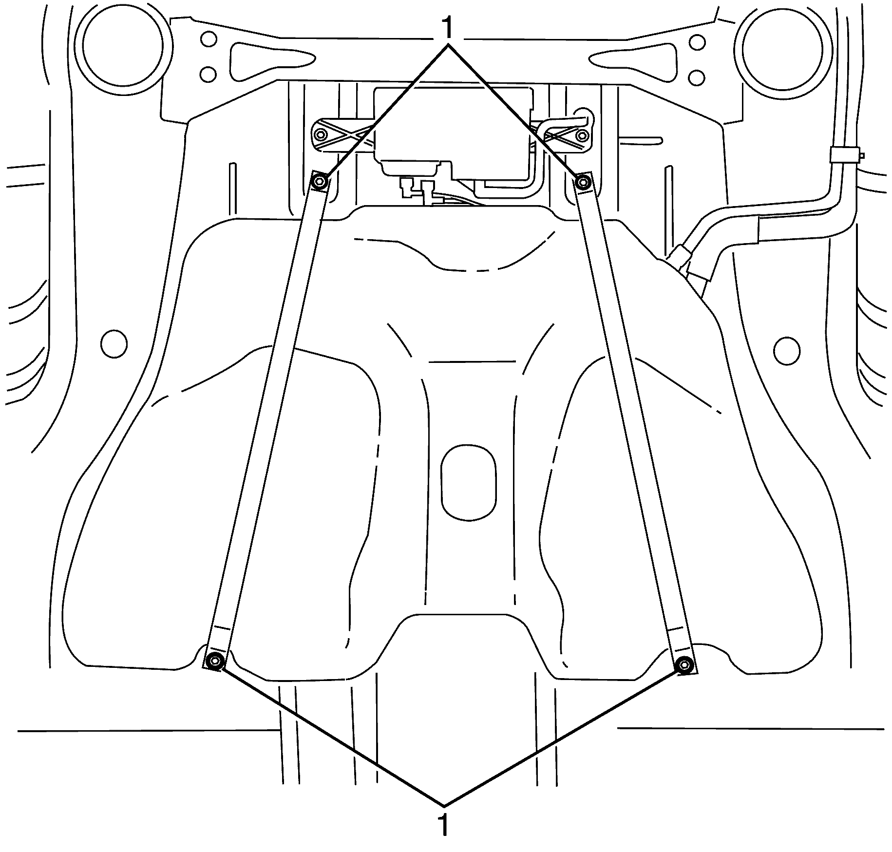
- Remove the rear frame to chassis retaining bolts (1) and (2) and discard.
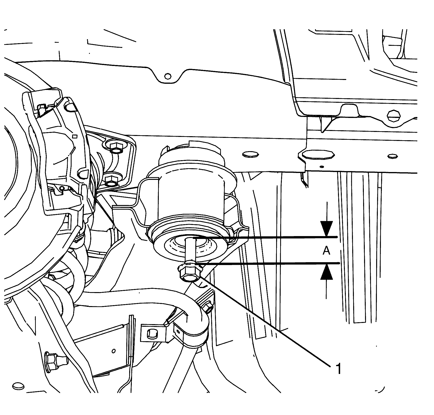
- Support the rear frame using the bolt (1) from the EN-48536 special tool kit . Repeat for the opposite side.
- Support the rear frame using the bolt (1) from the EN-48536 special tool kit . Repeat for the opposite side.
- Lower the rear frame approximately 50 millimetre's (2 in) (A) at the rear mounting surface between the rear frame and the chassis.
- This will allow clearance to access the fuel tank strap bolts.
- Remove the fuel tank heat shield. Refer to Fuel Tank Heat Shield Replacement .
- Disconnect the park brake rear cables from the park brake front cable equalizer bracket assembly. Refer to Parking Brake Front Cable Replacement .
- Disconnect the evapouritive emission line (2) from the evapourative emission canister (3). Refer to Plastic Collar Quick Connect Fitting Service .
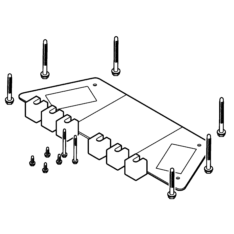
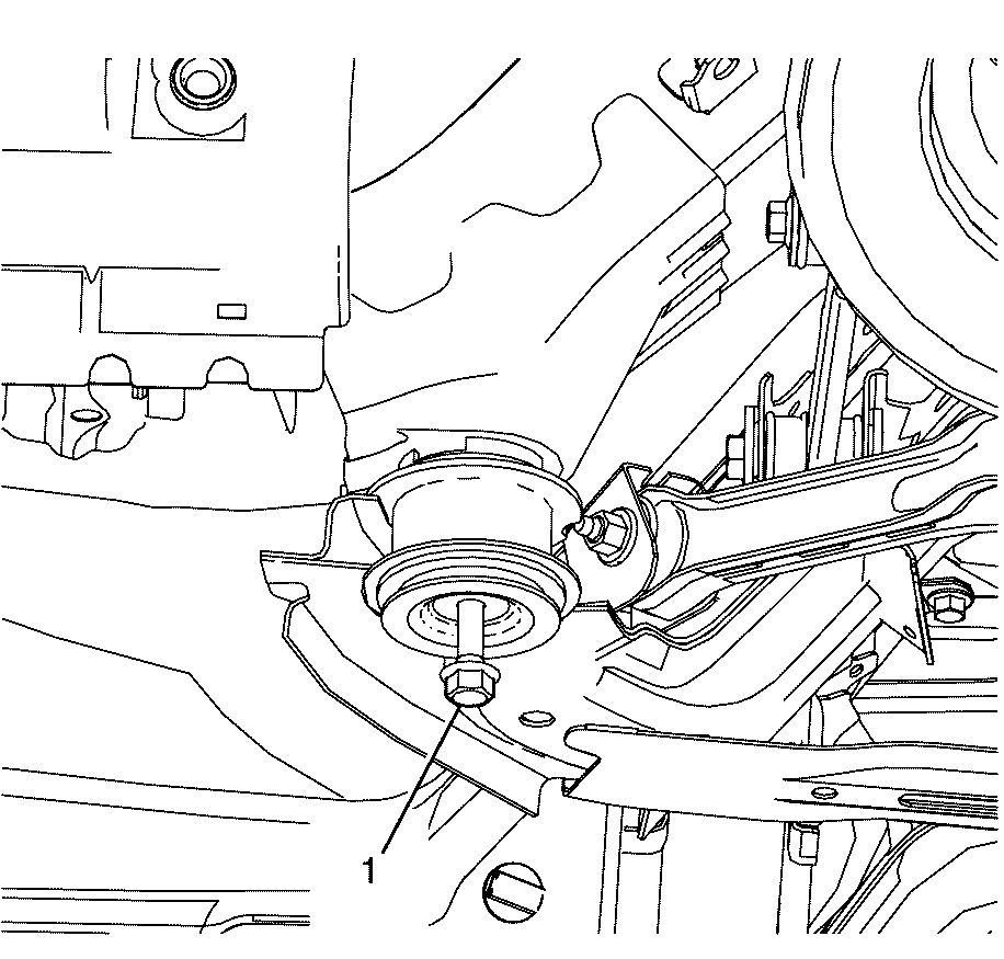
- Remove the fuel tank strap to chassis retaining bolts (1).
- Position the fuel tank straps away from the fuel tank.
- Carefully bend the fuel tank straps enough to allow the fuel tank to be removed.
- With the aid of an assistant, carefully lower the fuel tank from the vehicle.
- Remove the following components if replacing just the fuel tank.
Caution: Refer to Gasoline/Gasoline Vapors Caution in the Preface section.
Caution: Refer to Safety Glasses Caution in the Preface section.
Caution: Refer to Vehicle Lifting Caution in the Preface section.
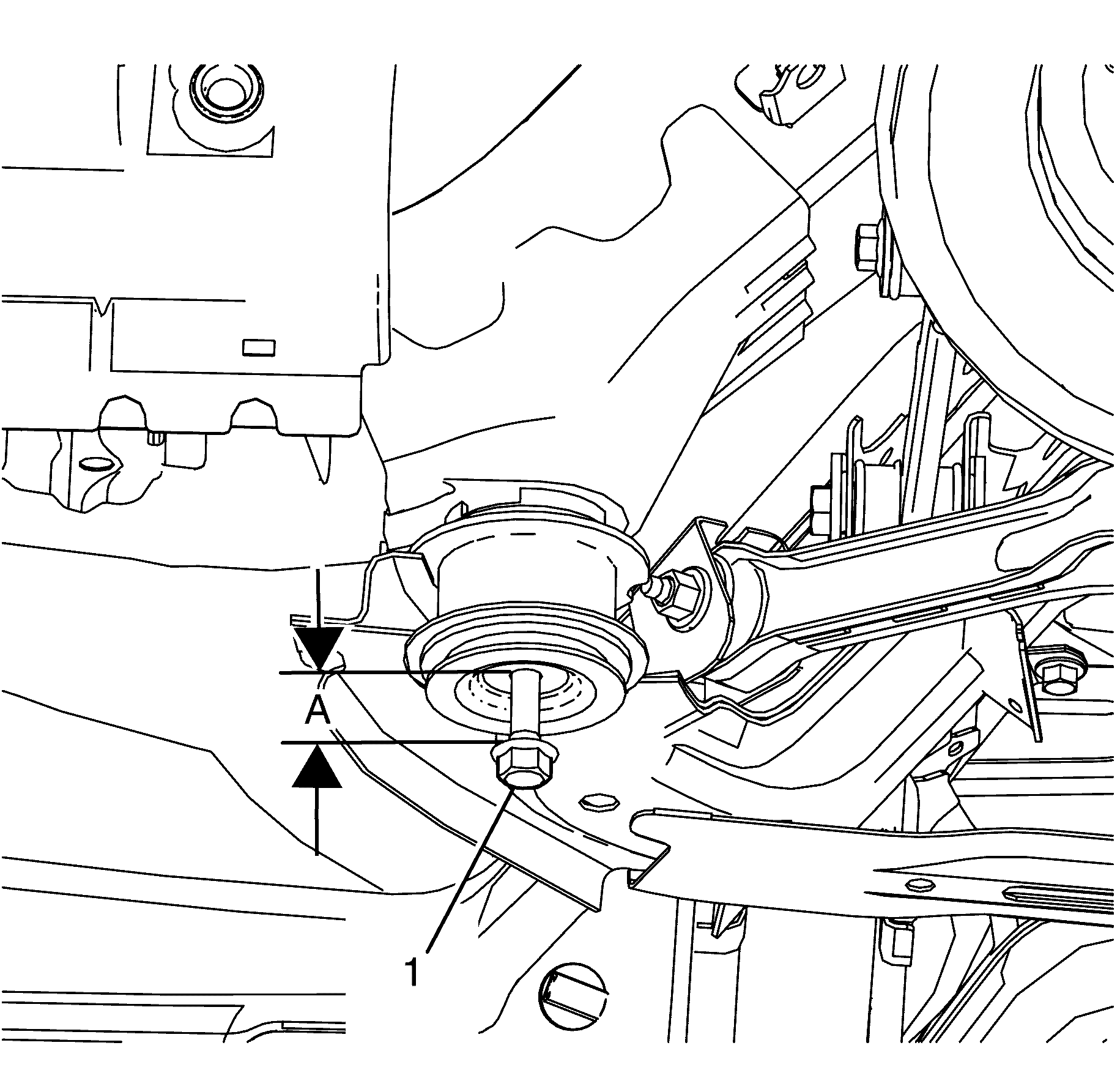
Important: When lowering the rear frame use care not to over extend the rear brake hoses.
Important: Make sure the following are free from the
surrounding components while lowering the fuel tank:
• The fuel tank wiring harness. • The fuel hoses at the chassis pipes.
| • | The primary fuel tank module - Refer to Primary Fuel Tank Module Replacement . |
| • | The secondary fuel tank module - Refer to Secondary Fuel Tank Module Replacement . |
Installation Procedure
- Install the following components if fuel tank replacement was necessary.
- With the aid of an assistant, carefully raise the fuel tank to the vehicle.
- Carefully install the fuel tank straps back to their original form.
- Position the fuel tank straps around the rear frame and upward into position, aligning the holes in the straps with the threaded holes in the chassis.
- Install the fuel tank strap bolts.
- Connect the evapourative emission line (2) to the evapourative emission canister (3). Refer to Plastic Collar Quick Connect Fitting Service .
- Raise the rear frame assembly using suitable tool.
- Remove the special tool EN-48536 bolt (1) from the rear frame. Repeat for the opposite side.
- Remove the special tool EN-48536 bolt (1) from the rear frame. Repeat for the opposite side.
- Using a suitable tool clean the threaded holes in the rear chassis.
- Install the NEW rear frame to chassis retaining bolts (2).
- After retaining bolts (1 and 2) are installed tighten to.
- Remove the support tool.
- Connect the fuel tank electrical connector (1).
- Refer to Plastic Collar Quick Connect Fitting Service , in order to connect the following to the chassis bundle:
- Install the evaporative emission (EVAP) line (1), listen for an audible click to confirm fitting.
- Connect the filler hose (2) to the fuel tank.
- Connect the park brake rear cables to the park brake front cable equalizer bracket assembly. Refer to Parking Brake Front Cable Replacement .
- Install the propeller shaft. Refer to Propeller Shaft Replacement .
- Install the exhaust system. Refer to Exhaust System Replacement .
- Install the right rear wheel. Refer to Tire and Wheel Removal and Installation .
- Refill the fuel tank.
- Inspect for fuel leaks.
| • | The primary fuel tank module--Refer to Primary Fuel Tank Module Replacement . |
| • | The secondary fuel tank module--Refer to Secondary Fuel Tank Module Replacement . |
Important: Make sure the following are properly routed
while raising the fuel tank:
• The fuel tank wiring harness. • The fuel hoses at the chassis pipes.
Important: Make sure the fuel tank straps are not pressed into the fuel tank.
Notice: Refer to Fastener Notice in the Preface section.
Tighten
Tighten the fuel tank strap bolts to 20 N·m
(15 lb ft).
Important: Rear frame retaining bolts must not to be fully tightened at this stage.
Do not fully tighten at this stage.
Tighten
| • | First Pass: Tighten the bolts to 65 N·m (48 lb ft) |
| • | Final Pass: Tighten the bolts a further 125 degrees. |
| • | The fuel feed line |
| • | The fuel EVAP hose |
Tighten
Tighten the fuel filler tube hose clamp (1)
to 4 N·m (35 lb in).
