For step by step programming instructions, please refer to the techline information
system (TIS) terminal.
Review the information below to make sure correct programming protocol.
Important:
| • | DO NOT program a control module unless you are directed by a service procedure
or you are directed by a service bulletin. Programming a control module at any other
time will not permanently correct a customer's concern. |
| • | It is essential that the Tech 2 and the TIS terminal are both equipped
with the latest software before performing service programming system (SPS). |
| • | Due to the time requirements of programming a controller, it is recommended
that an external power source be used to maintain system voltage. Stable battery voltage
is critical during programming. Any fluctuation, spiking, over voltage or loss of
voltage will interrupt programming. To ensure trouble-free programming, it is recommended
to use one of the following external power sources: |
| - | A Midtronic PCS charger |
| - | A fully charged 12V jumper or booster pack disconnected from the AC voltage
supply |
| • | Input requests across the GMLAN serial data circuits during recalibration
can cause calibration issues. Due to the control modules common architecture, an inadvertent
input may, in a rare instance, activate other control modules that have been commanded
to remain silent during the recalibration of another control module possibly causing
a programming event to fail. |
| • | Refrain from altering vehicle controls, opening and closing doors etc.
while a control module is being recalibrated. |
| • | After a vehicle is shut down and the door is closed the vehicle will begin
a power shut down process and it may take up to 40 minutes for all control modules
to enter sleep mode, whereby the vehicle is drawing 35 - 40 ma of sleep power. |
| • | It is essential that the scan tool and the TIS terminal are both equipped
with the latest software before performing service programming system (SPS). |
| • | Some modules will require additional programming/setup events performed
before or after programming. |
| • | Some vehicles may require the use of a CANDi module for programming. |
| • | Review the appropriate service information for these procedures. |
| • | DTCs may set during programming. Clear DTCs after programming is complete. |
Make sure the following conditions are met before programming a control module:
| - | There is not a charging system concern, i.e battery voltage is greater
than 12 volts but less than 16 volts. All charging system concerns must be repaired
before programming a control module. |
| - | Battery voltage is greater than 12 volts but less than 16 volts. |
| - | Turn OFF or disable any system that may put a load on the vehicle's battery,
such as the following components: |
| • | Heating, ventilation, and air conditioning (HVAC) systems |
| • | Engine cooling fans, radio, etc. |
| • | The ignition switch must be in the correct position. The scan tool prompts
you to turn ON the ignition, with the engine OFF. DO NOT change the position of the
ignition switch during the programming procedure, unless instructed to do so. |
| • | Make certain all scan tool connections are secure, including the following
components and circuits: |
| - | The RS-232 communication cable port |
| - | The connection at the data link connector (DLC) |
| - | The voltage supply circuits |
| • | DO NOT disturb the scan tool harnesses while programming. If an interruption
occurs during the programming procedure, programming failure or control module damage
may occur. |
| • | DO NOT turn OFF the ignition if the programming procedure is interrupted
or unsuccessful. Make sure that all control module and DLC connections are secure
and the TIS terminal operating software is up to date. Attempt to reprogram the control
module. If the control module cannot be programmed, replace the control module. |
Service Programming System (SPS) Pass-Thru
Important: Some module require you the turn the ignition
off for 30 secs. Only do so if instructed by the Scan tool.
- Select Service Programming System from TIS Terminal, follow the on-screen
instructions.
- You will be presented with multiple options select Tech 2 Legacy Pass-thru.
- Select re-program ECU and click the next button. Follow the on-screen
instructions.
- Select Salesmake, Model year, Vehicle type, Carline.
- The next screen will display the Vehicle Identification Number, if this
is correct click next.
- Select the module you wish to program for calibrate then select the programming
type.
- If the module requires a update calibration, select next.
- Select Clear DTC's.
Service Programming System (SPS) Step-by-Step
Notice: Refer to General Repair Instructions in the Preface section.

Important: The battery must be fully charged and it
MUST not be connected to a battery charger during the SPS process.
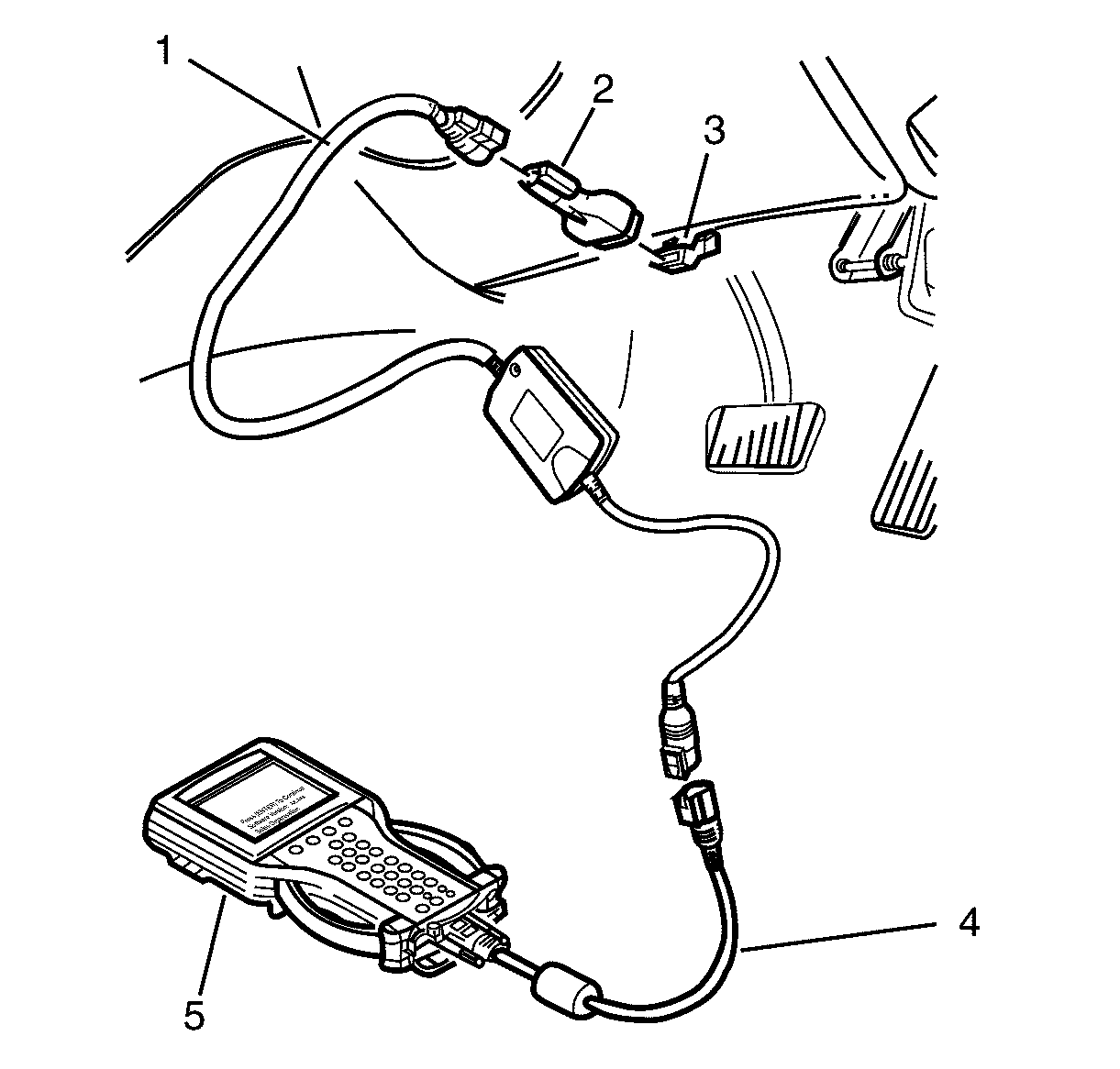
- Connect Scan tool to DLC cable (4) to the CAndi module and cable assembly (1).
- Securely connect the DLC adapter (2) to the CAndi module and cable assembly
(1).
- With the CAndi module and cable assembly (1 and 2) securely connected,
install the DLC adapter (2) into the DLC (3).
- Press the scan tool PWR button to turn on scan tool.
- When the scan tool title screen is displayed, press ENTER to continue.
- Select F1: Service Programming System (SPS).
- Select F0: Request Info and follow the instructions on the screen.
- If there is data already stored, scan tool will display the stored data.
Press the Continue Soft Key to request new information.
- If there is no data stored in the scan tool then a Model Year selection
screen will be displayed.
- Using the arrow keys select the correct Model Year for the vehicle you
are working on and press ENTER
- The scan tool will then display a Vehicle Type(s) selection screen. Select
the appropriate vehicle type with the arrow keys and then press ENTER.
- The scan tool will then display the System Selection Menu screen. The
desired system can be selected from the System Selection menu with the function keys
or with arrow keys and then press ENTER.
- Turn the ignition off and then press the Okay soft key to continue.
- When Ignition switched off! is displayed, make sure that the ignition
is switched off and then press the Okay soft key to continue.
Important: Make sure that the headlights are off when
the ignition is turned on.
- Turn off all power consuming devices! (i.e. A/C. Radio, Headlamps etc). Turn
on ignition with engine off! Be sure the battery is fully charged. Press the Okay
soft key to continue.
Important: If programming a Service Replacement ECM/TCM/PCM
the VIN will not be displayed.
- The scan tool will then read and display the Vehicle Identification Number (VIN)
and ECU data. Follow the instructions displayed on the scan tool screen.
- Turn the scan tool off.
- Connect the scan tool and security hardware key to the serial port of
a Personal Computer (PC) with TIS 2000 installed. If your security hardware key is
the serial type, go to step 17. If your hardware key is the parallel type, go to step
22. If your hardware key is the USB type, go to step 27.

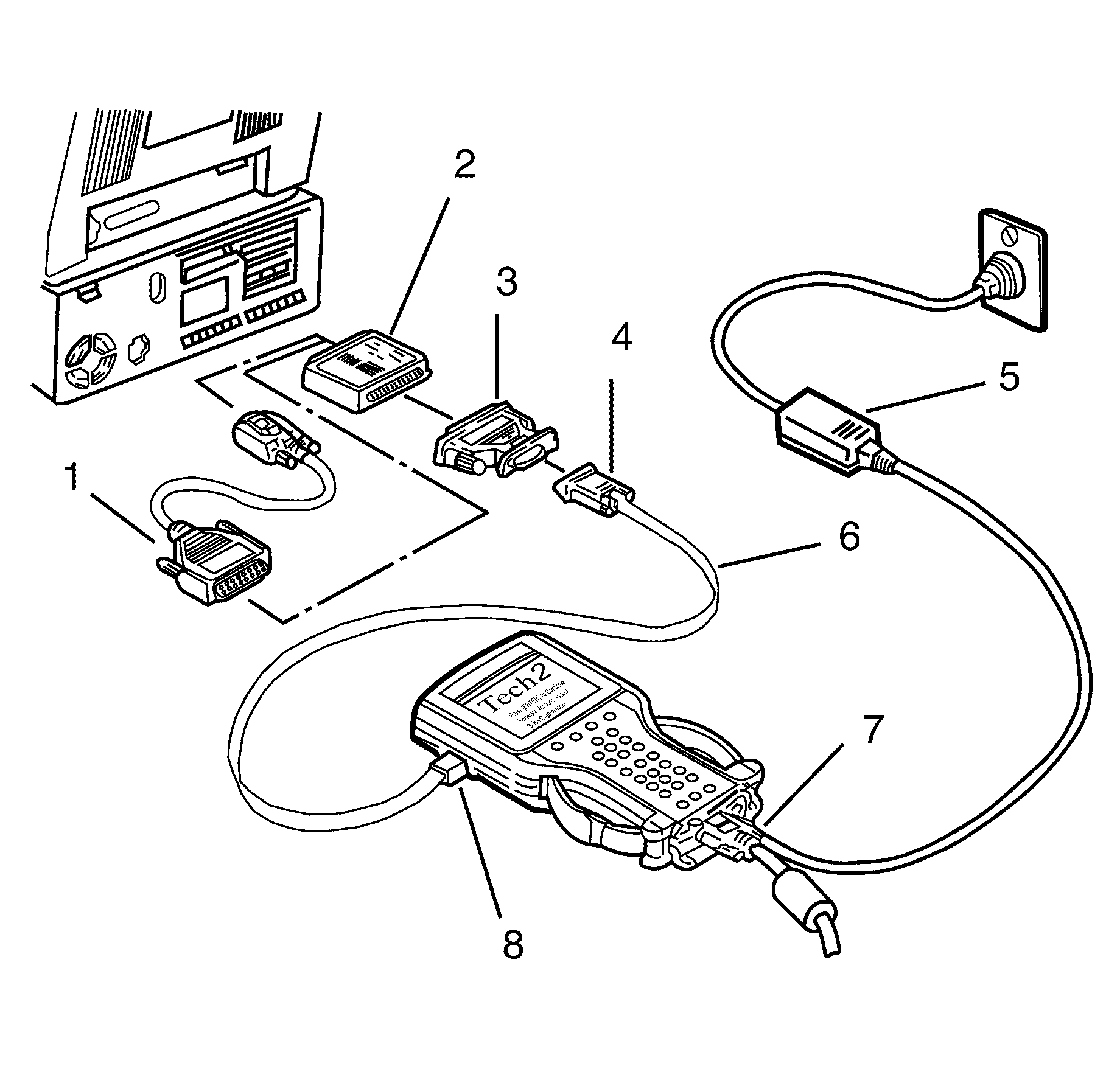
- Connect the RS-232 cable (6) to the scan
tool RS-232 communication port (8).
- Connect the other end of the RS-232 cable to the DB-9 adapter (4) and
then connect the DB-9 adapter to the 25/9 pin adapter (3).
Notice: Refer to General Repair Instructions in the Preface section.
- Connect the 25/9 pin adapter (3) to the Serial Security Hardware Key (2) and
then connect the Serial Security Hardware Key to the serial port of a Personal Computer
(PC) with TIS 2000 installed.
- Connect the power supply (5) to the scan tool power supply jack (7). Press
the PWR button to turn on scan tool. Scan tool should now be at the title display
screen.
- Now go to step 31.

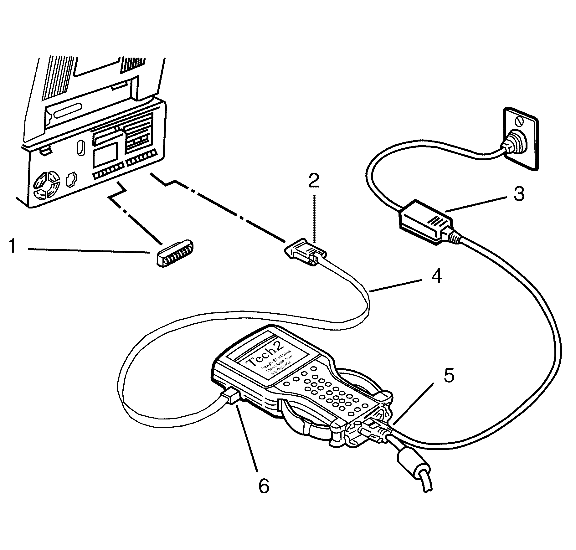
- Connect the RS-232 cable (4) to the scan
tool RS-232 communication port (6).
- Connect the other end of the RS-232 cable to the DB-9 adapter (2) and
then connect the DB-9 adapter to the Comms port of the Personal Computer (PC) with
TIS 2000 installed.
- Connect the Parallel Security Hardware Key (1) to the serial port of the
Personal Computer (PC) with TIS 2000 installed.
- Connect the power supply (3) to the scan tool power supply jack (5). Press
the PWR button to turn on scan tool. scan tool should now be at the title display
screen.
- Now go to step 31.

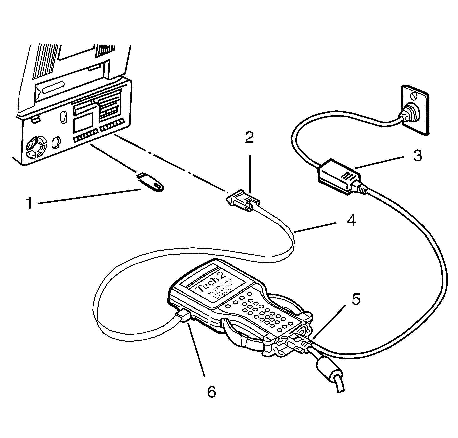
- Connect the RS-232 cable (4) to the scan
tool RS-232 communication port.
- Connect the other end of the RS-232 cable to the DB-9 adapter (2) and
then connect the DB-9 adapter (2) to the Comms port of the Personal Computer (PC)
with TIS 2000 installed.
- Connect the USB Security Hardware Key (1) to the USB port of the Personal
Computer (PC) with TIS 2000 installed.
- Connect the power supply (3) to the scan tool power supply jack (5). Press
the PWR button to turn on scan tool. scan tool should now be at the title display
screen.
- Open TIS 2000 by double clicking the TIS 2000 Icon.
- The default user of TIS2000 is called "TIS". This user does not have a
password. Click the "OK" icon to continue.
- From the TIS 2000 Main Menu click on the SPS icon to start the SPS application.
- At Select Diagnostic Tool and Programming Process click on desired selections
for:
| • | Diagnostic tool being used: TECH 2. |
| • | Whether you are reprogramming an existing control unit or programming
a new control unit. |
| • | Select ECU location: Vehicle. |
- After making your selections, select Next>.
- Note: At this point you should have already Requested Info from the Vehicle
and scan tool should be connected to the serial port of a Personal Computer (PC) with
TIS 2000 installed.
Select Next>. to continue.
- Confirm VIN or enter correct VIN, if required, then select Next>.
- If the vehicle data is correct Select Next> to continue.
- Select system type. All available modules appear on screen. The module
to be programmed must be selected, select Next> to continue.
Important: If VCI is required refer to TAS (Technical
Assistance Service).
- Select programme type. Two options appear on screen, normal and VCI. Select
normal then Next> to continue.
Important: The options selected must match the vehicle.
- If you wish to change any of the programming options, select the option you
wish to change and then select delete. A list of the options available will then be
displayed and the select Next> to continue.
- A Summary screen will appear, allowing you to confirm your selection.
Select Reprog to continue.
- A Transfer Data screen will appear. Select Reprog button to initiate download
of new calibration file to scan tool. The screen will track progress of download.
- After download is complete a screen will appear instructing you to connect
scan tool to vehicle to complete programming process. Close the SPS application to
return to TIS 2000 main menu; power down and then disconnect scan tool from PC.
- Return to the vehicle and complete the SPS process.
Notice: Refer to General Repair Instructions in the Preface section.

Important: The battery must be fully charged and it
MUST not be connected to a battery charger during the SPS process
- Connect CAndi module to DLC adapter cable (1) to the scan tool output connector
(4).
- Connect the CAndi module to DLC adapter cable (1) to the DLC adapter (2)
securely connect the DLC adapter (2) with the DLC (3).
- Press the scan tool PWR button to turn on scan tool.
- When the scan tool, title screen is displayed, press ENTER to continue.
- Select F1: Service Programming System (SPS).
- F1: Program ECU will be flashing on the scan tool display. Scan tool is
ready for ECU programming.
- Select F1: Program ECU and follow the instructions on the scan tool screen.
- Turn off all power consuming devices! (i.e. A/C. Radio, Headlamps etc).
Turn on ignition with engine off! Be sure the battery is fully charged. Press the
Okay soft key to continue.
- TECH 2 will begin programming the ECU. The scan tool screen display will
indicate the progress of the download as a percentage.
- Programming successful ! will be displayed when programming is completed.
- Press the Exit soft key.
- Turn off scan tool and disconnect it from the vehicle DLC.


