For 1990-2009 cars only
Removal Procedure
- Raise and support the vehicle. Refer to Lifting and Jacking the Vehicle.
- Remove the front tire and wheel assemblies. Refer to Tire and Wheel Removal and Installation.
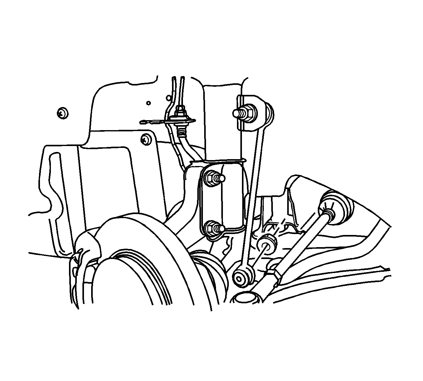
- Remove the left and the right stabilizer shaft-to-stabilizer link nuts.
- Lower the crossmember slightly in order to access the stabilizer shaft insulator clamp bolts. Refer to Front Suspension Crossmember Replacement.
- Remove the stabilizer shaft insulator clamp bolts.
- Remove the stabilizer shaft insulator clamps.
- Remove the insulators.
- Remove the stabilizer shaft.
Installation Procedure
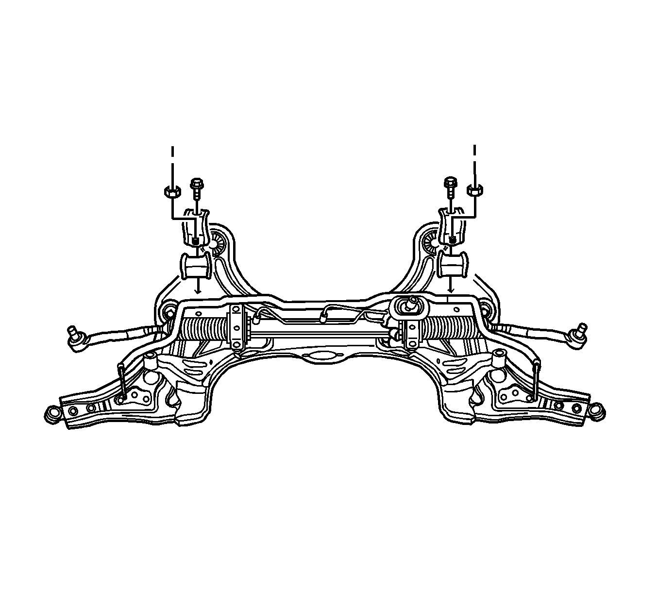
- Install the stabilizer shaft to the crossmember.
- Install the insulators to the stabilizer shaft.
- Install the clamps to the insulators.
- Install the stabilizer shaft clamp bolts.
- Raise and install the crossmember. Refer to Front Suspension Crossmember Replacement.
- Raise and support the front lower control arms with jacks.
- Install the left and the right stabilizer links and the nuts to the stabilizer shaft.
- Install the front tire and wheel assemblies. Refer to Tire and Wheel Removal and Installation.
- Remove the jacks.
- Lower the vehicle.
Important: There must be no grease or dirt on the stabilizer shaft. Verify the stabilizer shaft is clean.
Important: Do not tighten the bolts yet.
Notice: Refer to Fastener Notice in the Preface section.
Tighten
| • | Tighten the stabilizer shaft-to-stabilizer link nuts to 47 N·m (35 lb ft). |
| • | Tighten the stabilizer shaft clamp bolts to 25 N·m (18 lb ft). |
