Tools Required
EN-48536 Frame Support Tool (Engine Lower 65mm Kit)
Removal Procedure
- Disconnect the negative battery cable. Refer to Battery Negative Cable Disconnection and Connection.
- Remove engine air intake ducting.
- Remove radiator retaining clips.
- Disconnect the evap purge pipe.
- Raise and suitably support the vehicle. Refer to Lifting and Jacking the Vehicle.
- Remove the propeller shaft. Refer to Propeller Shaft Replacement.
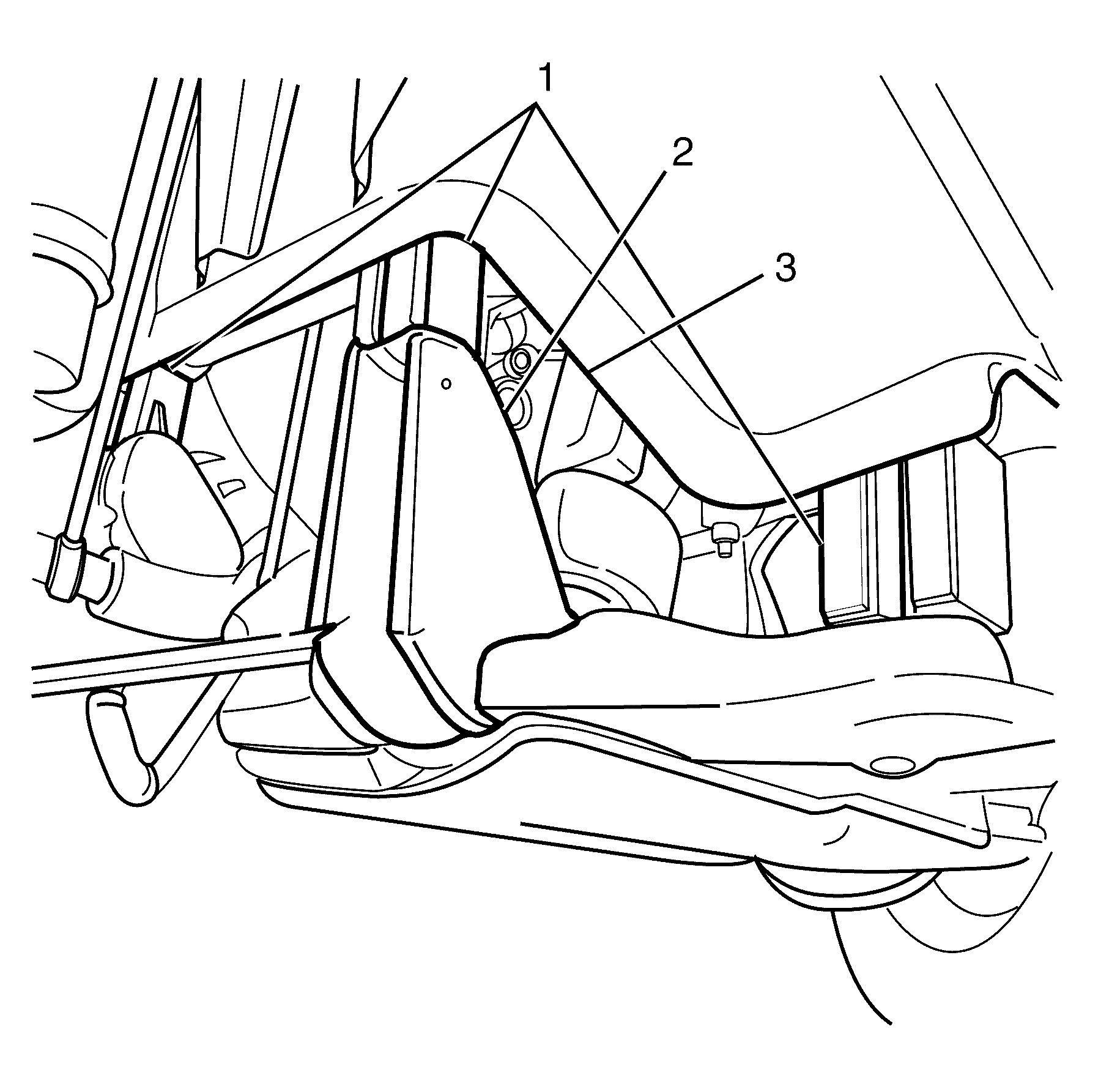
- Remove the air deflector front (1). Refer to Front Air Deflector Replacement.
- Remove the splash shield.
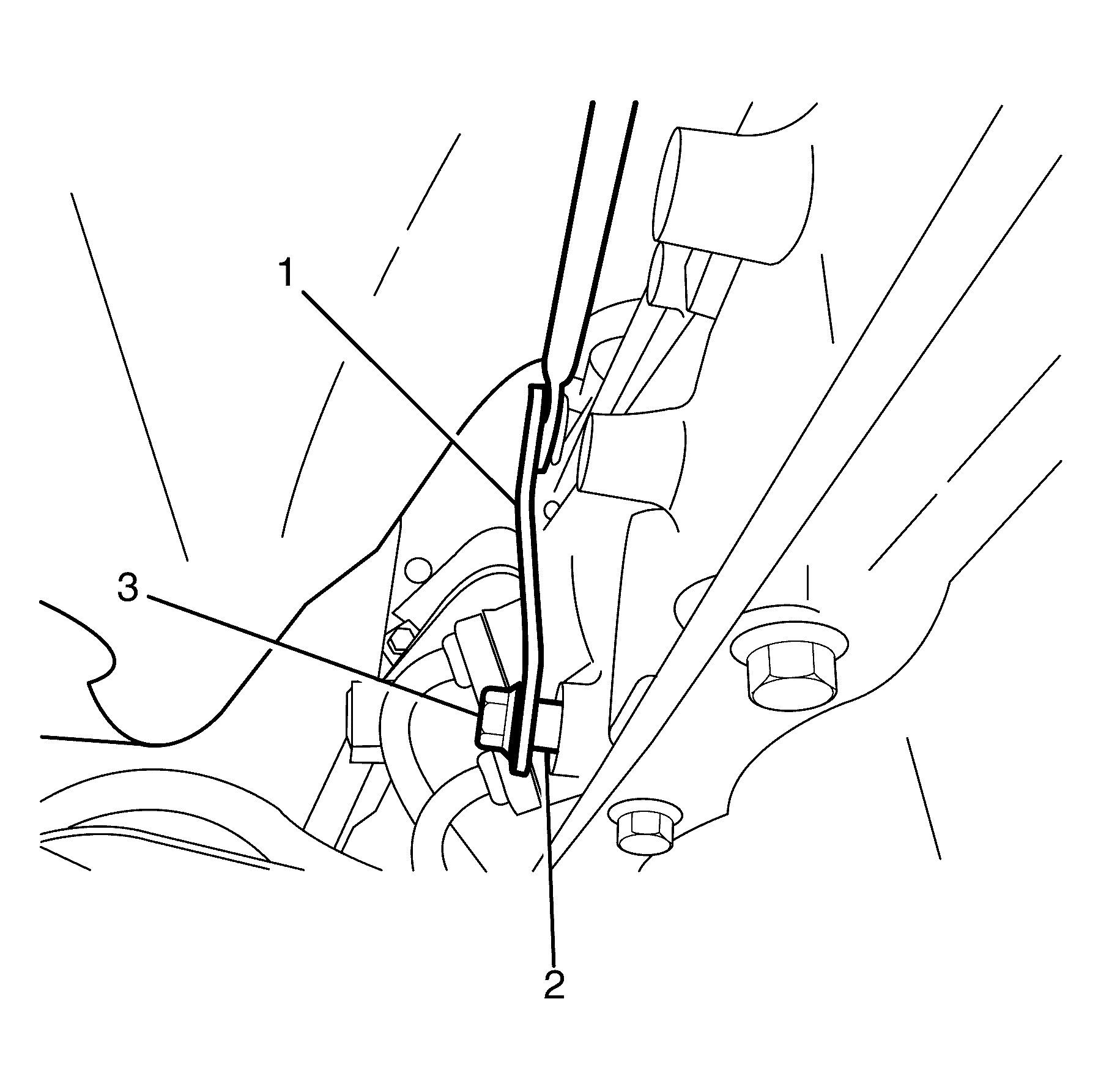
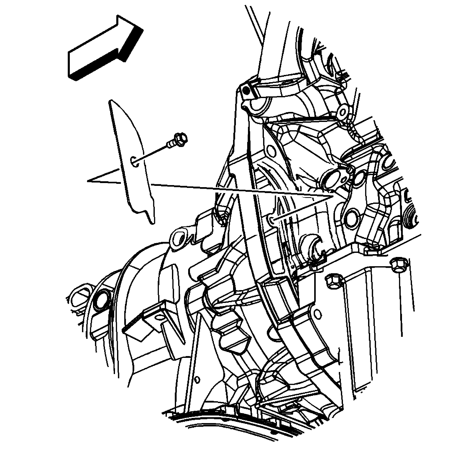
- Remove the transmission manual shift shaft retaining nut (3).
- Disconnect the shift linkage (1) from the transmission.
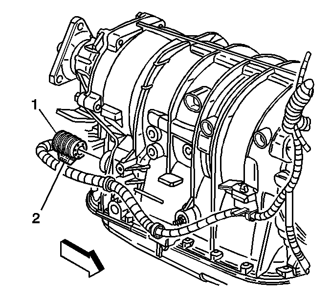
- Disconnect the transmission wiring harness connector (1) from the transmission by rotating the locking latch (2) counter clockwise.
- Disconnect the wiring harness clips from the transmission, and position the wiring harness aside.
- Remove the starter motor to gain access to the torque converter bolts. Refer to Starter Motor Replacement.
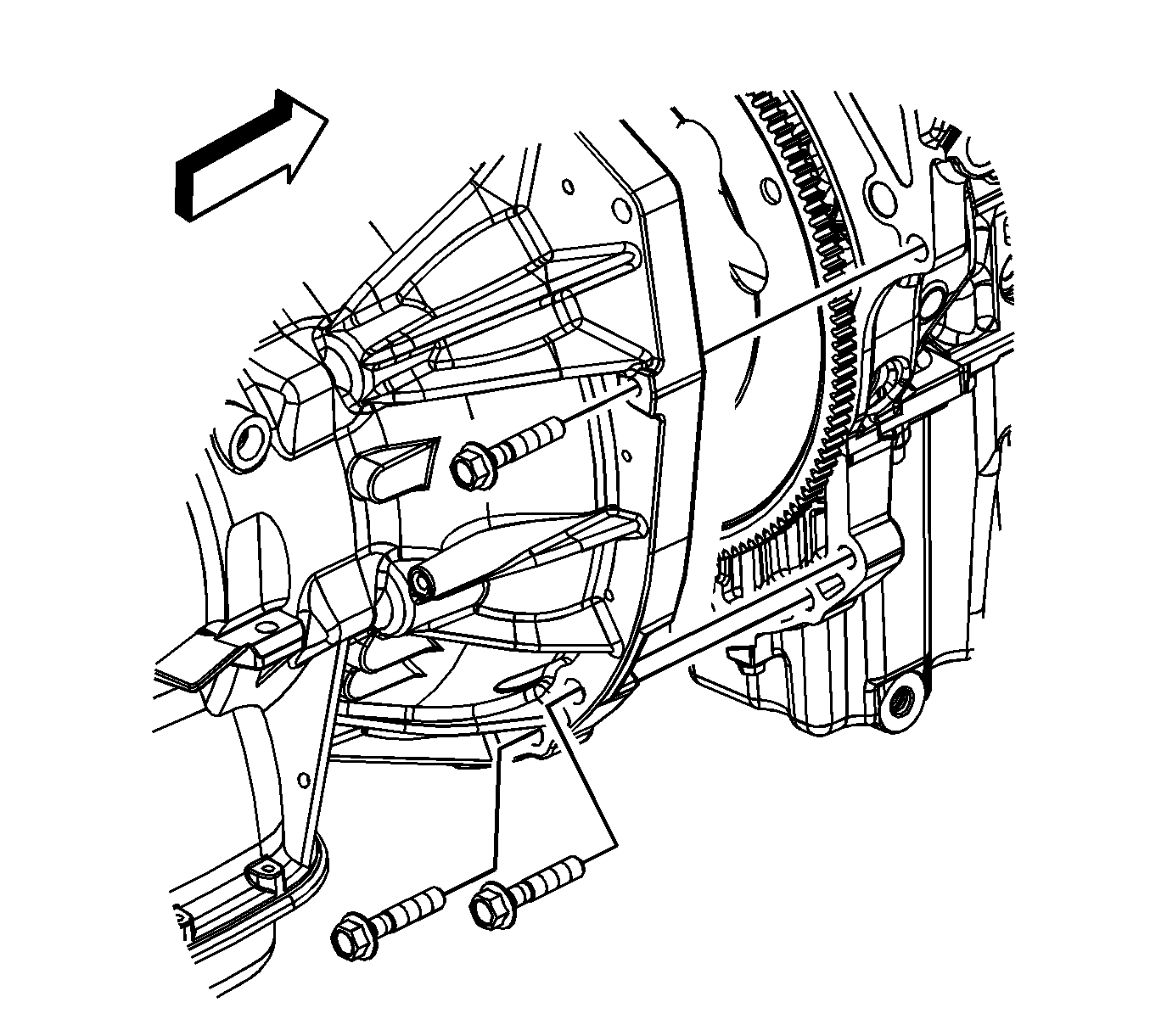
- Mark the torque converter to flexplate/flywheel orientation to make sure proper realignment.
- Repeat the following steps for all 3 torque converter bolts:
- Using inspection hole push torque converter back towards transmission pump
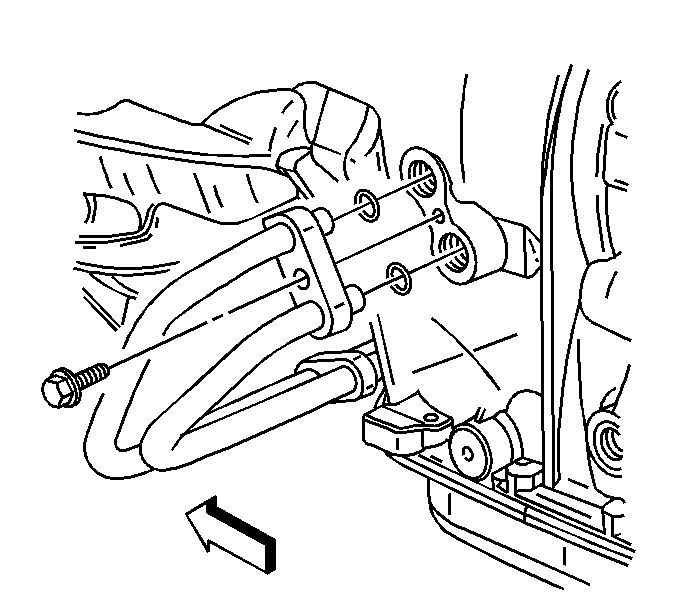
- Place an oil drain pan under the transmission fluid cooler pipes.
- Remove the bolt securing the transmission fluid cooler pipes brace to the engine.
- Disconnect the fluid cooler pipes from the transmission.
- Plug the open outlet ports to prevent fluid loss and contamination.
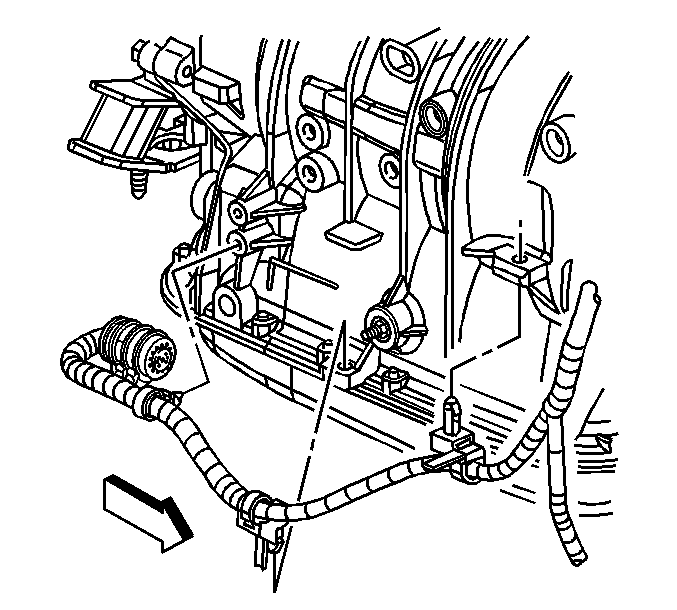
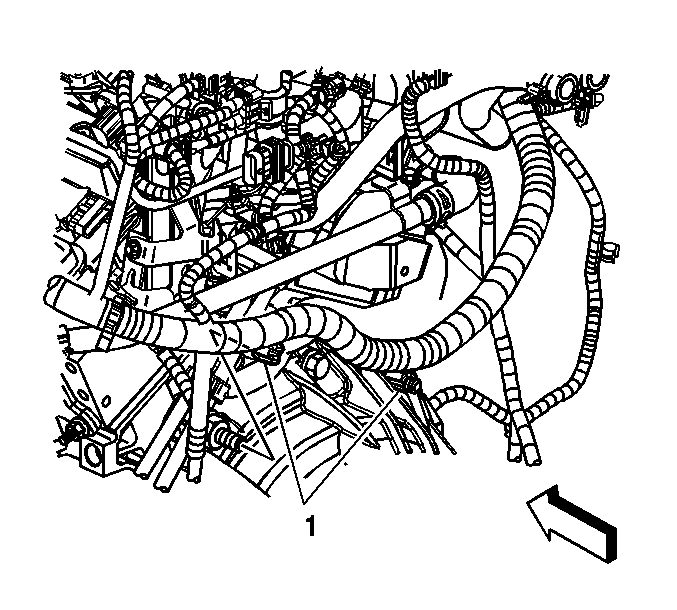
- Disconnect the engine wiring harness retaining clips (1) to the transmission mounting bolts.
- Disconnect the steering shaft from the steering rack.
- Remove the engine close out cover.
- Support the power train with a suitable jack or table.
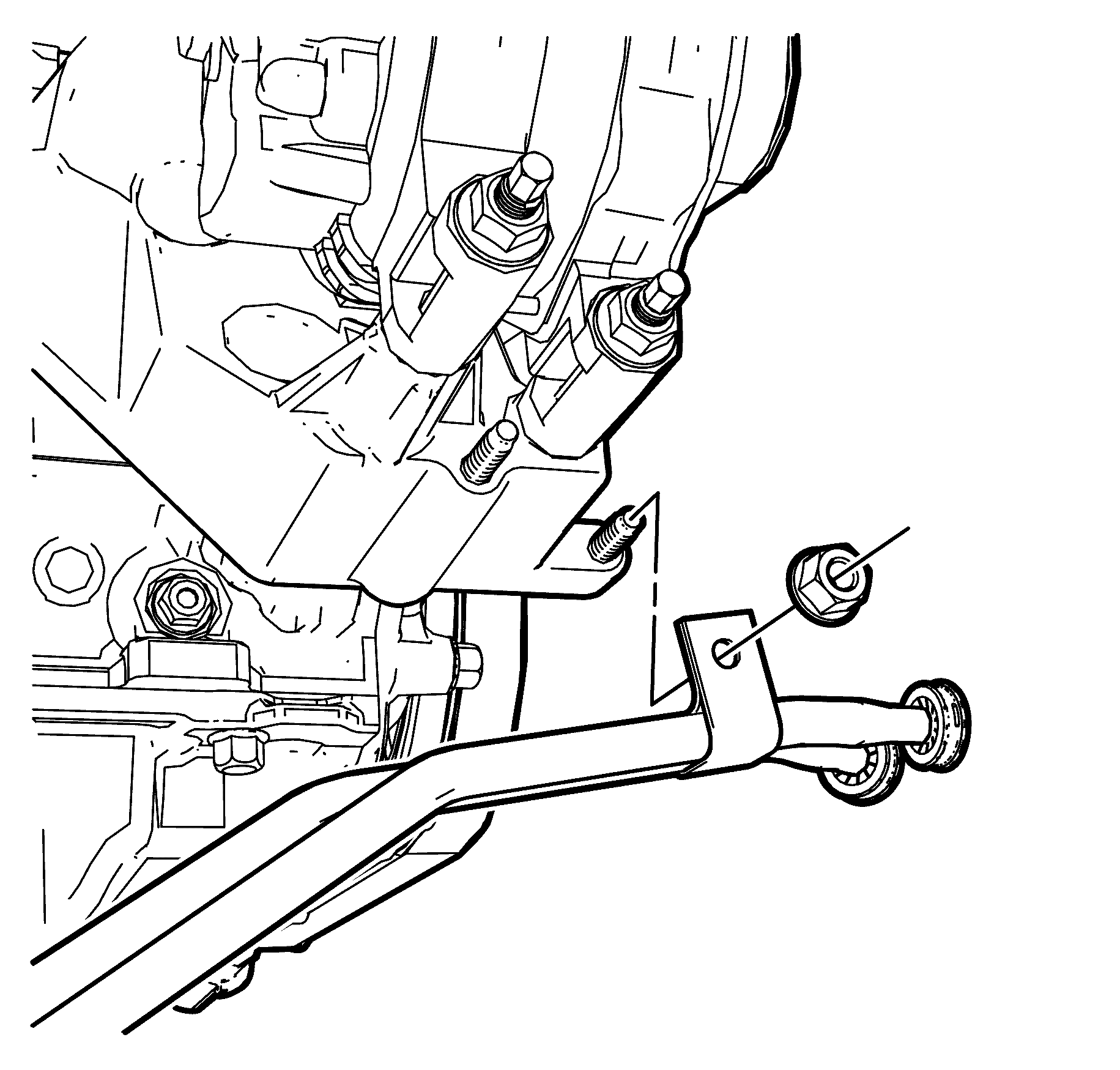
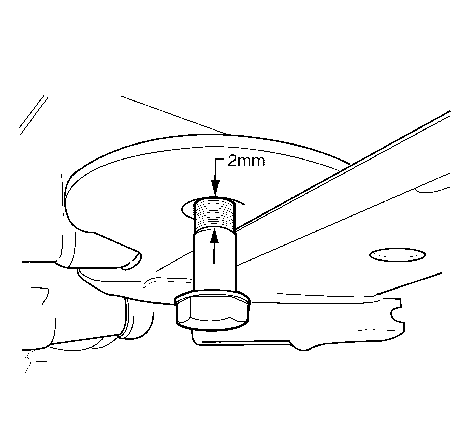
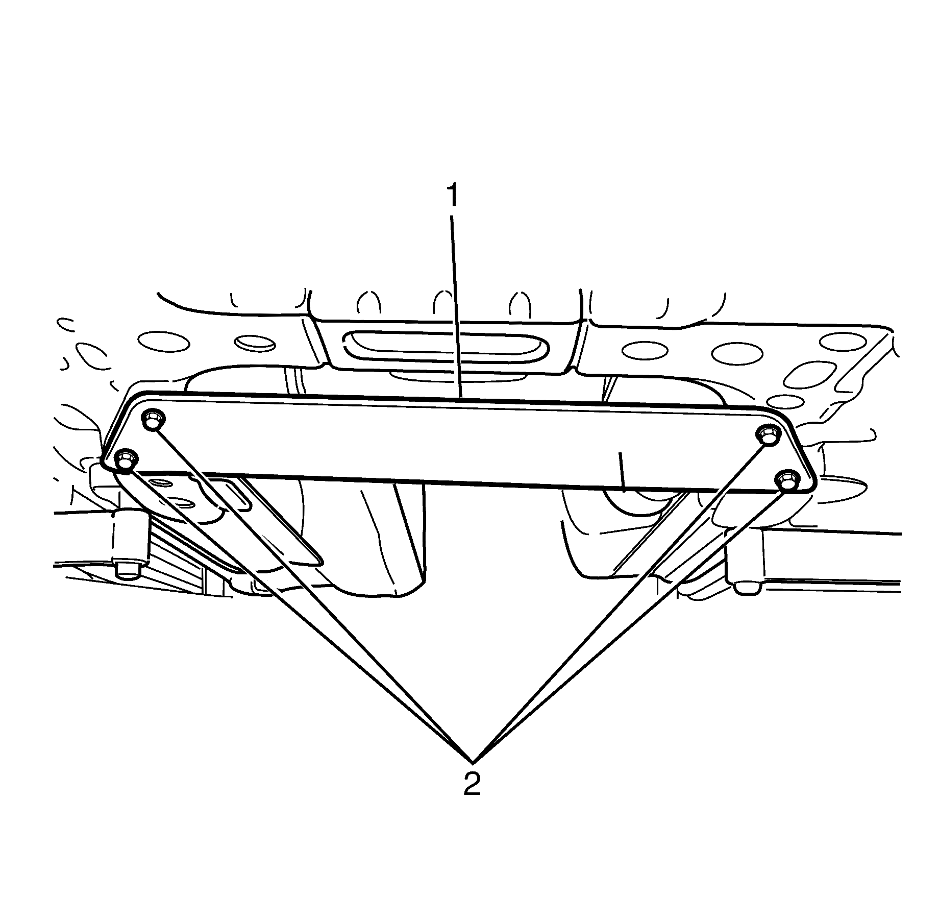
- Remove the front sub frame rear retaining bolts and fit bolts from special tool kit EN-48536
- Install bolt till stepped shank (1) is 2mm below sub frame (2).
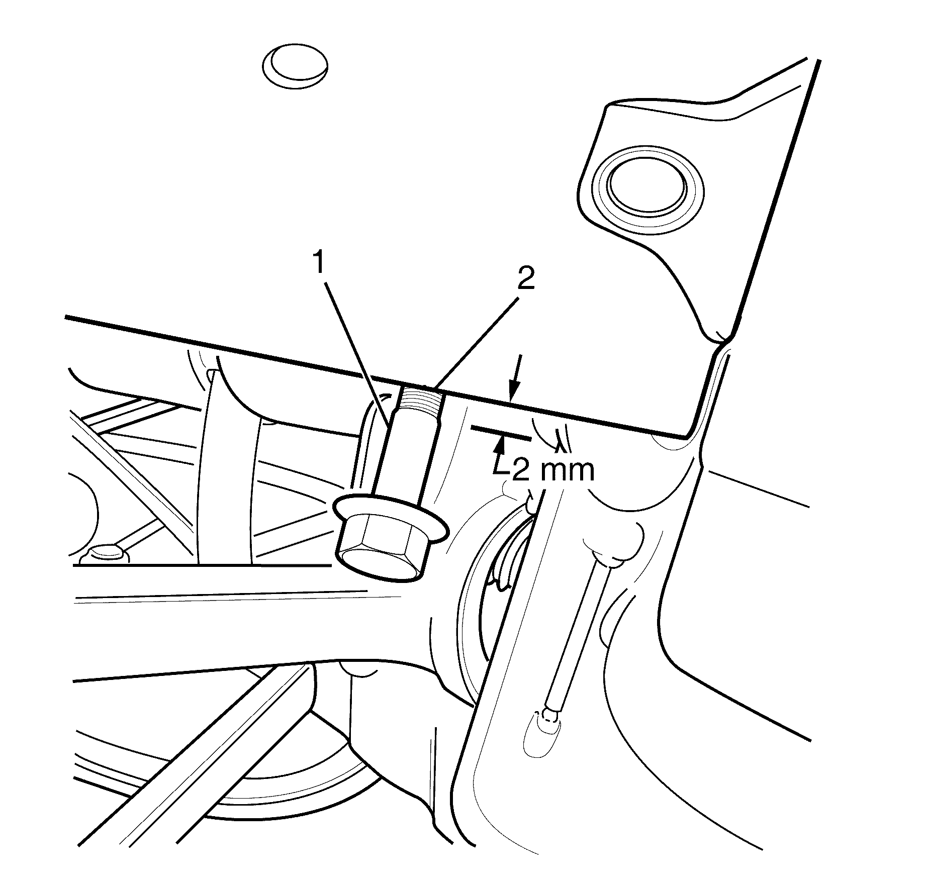
- Remove the front sub frame front retaining bolts and fit bolts from special tool kit EN-48536
- Install bolt till stepped shank (1) is 2mm below chassi rail flange (2).
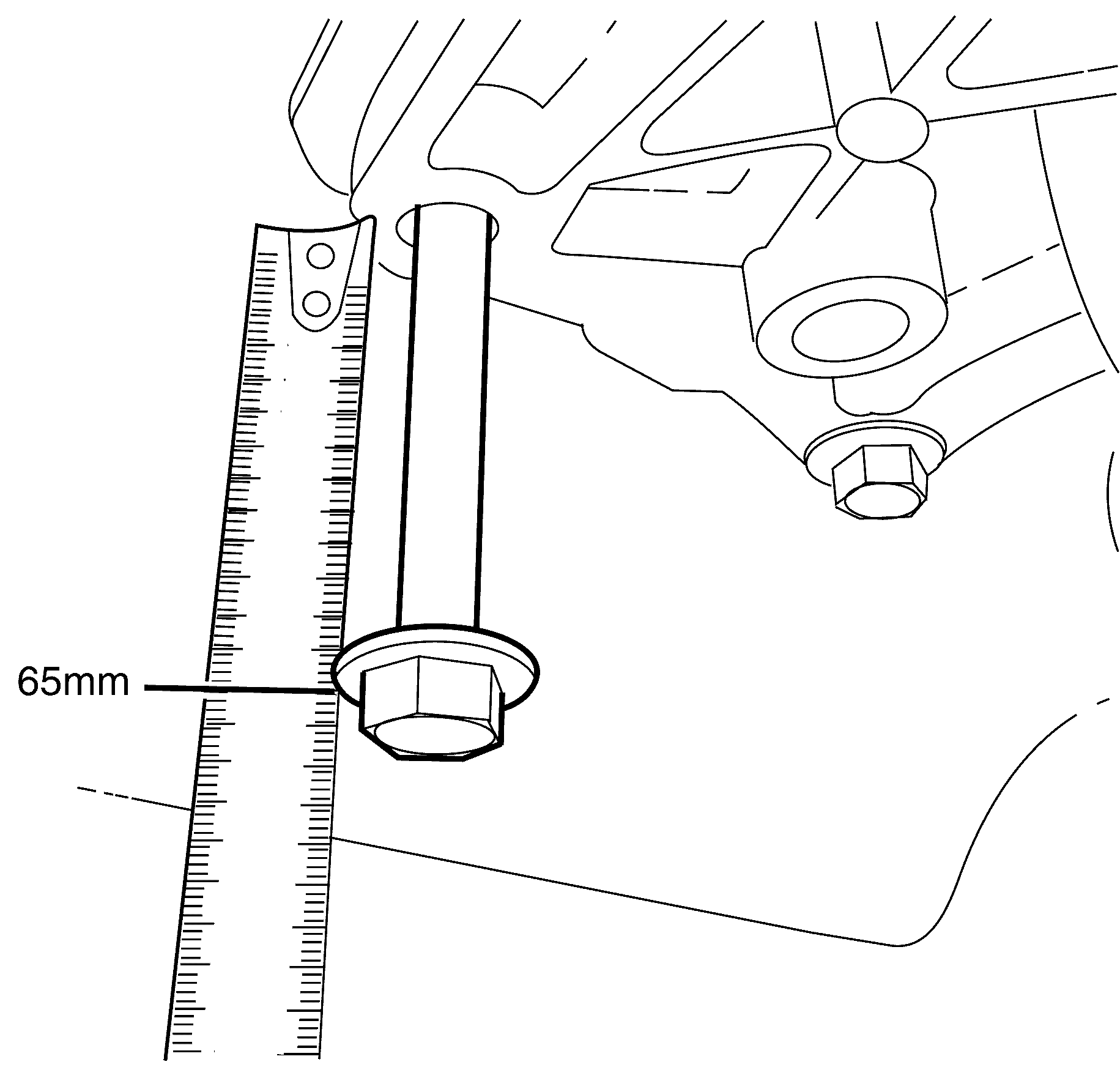
- Remove all four transmission mount to body retaining bolts and install two bolts from special tool kit in diagonal holes e.g Left hand front and Right hand rear.
- Install the bolts until 65mm is measured between the bolt heads (1) and transmission mount (2).
- Remove the front sub frame middle bolts.
- Lower the power train slowly until the subframe and transmission mount are resting on bolts.
- Insert the 65mm spacer blocks (1) between the subframe (2) and chassis rails (3).
- Tension the front sub frame front and rear bolts.
- Install and tension the middle sub frame bolts.
- Remove the supporting jack or table
- Install engine support plate (1) to the front sub frame.
- install the engine support plate retaining bolts (2).
- Remove the transmission retaining bolts.
- Pull the transmission free from the engine dowels.
- Carefully lower the transmission from the vehicle.
- Flush the transmission oil cooler. Refer to Transmission Fluid Cooler Flushing and Flow Test.
Important: NEW torque converter retaining bolts will be required each time the torque converter bolts are removed.
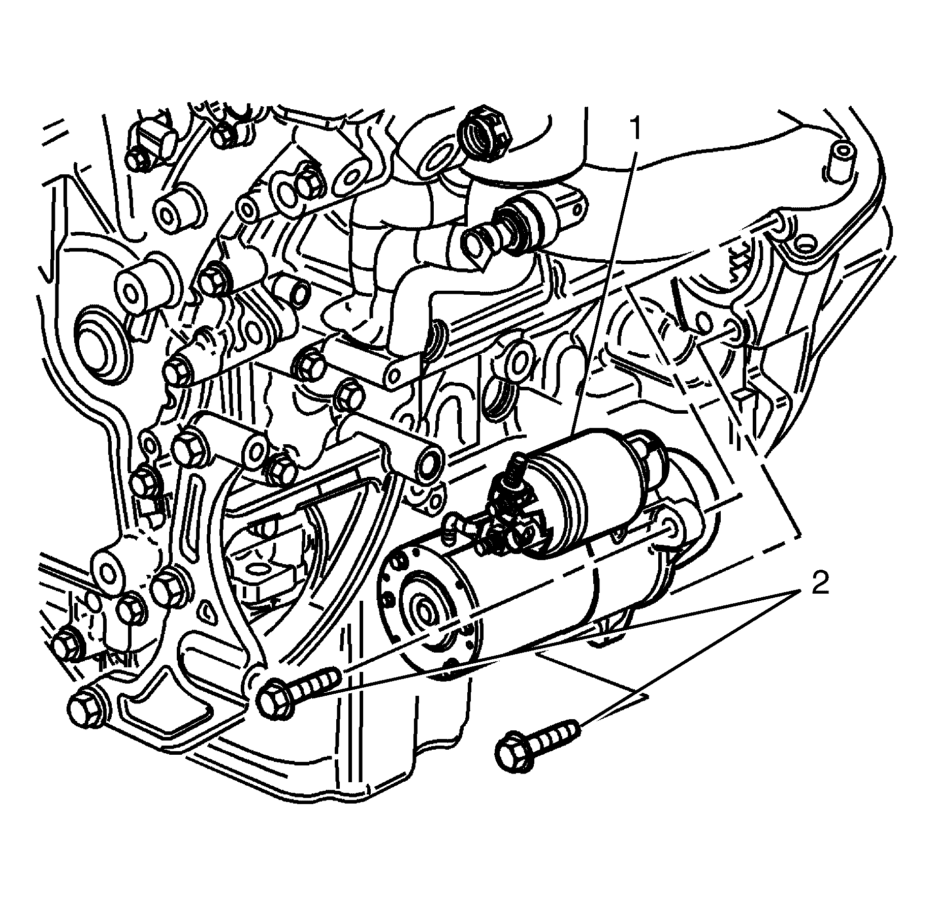
| 15.1. | Rotate the harmonic balancer centre bolt clockwise ONLY, in order to align the torque converter bolt with the starter motor opening in the engine block. |
| 15.2. | Remove and discard the torque converter bolt. The bolt is self locking and is NOT reusable. |
Important: The engine mounts must NOT bend or deflect from the vertical position, damage to the mount will occur.
Tighten
Tighten the bolts to 95 N·m (70 lb. ft).
Tighten
Tighten the bolts to 95 N·m (70 lb. ft).
Tighten
Tighten the bolts to 10 N·m (89 lb. in).
Important: Ensure clearance is maintained between the
transmission and the following:
• The catalytic converters • The wiring harnesses • The cooler pipes • The propeller shaft
Installation Procedure
- Using the transmission jack, carefully raise the transmission to the vehicle.
- Align the transmission with the engine dowels.
- Install the right hand side transmission retaining bolts.
- Install the remaining transmission retaining bolts.
- Install the engine close out cover.
- Remove the engine and transmission lowering blocks and engine balance plate.
- Raise the powertrain back up into the engine bay and install the front sub frame bolts.
- Connect the engine wiring harness retaining clips (1) to the transmission mounting bolts.
- Install the steering shaft to the steering rack.
- Lubricate the O-rings seals with automatic transmission fluid.
- Install the O-rings seals onto the cooler pipes prior to inserting the cooler pipes into the transmission.
- Insert the transmission fluid cooler pipes into the transmission.
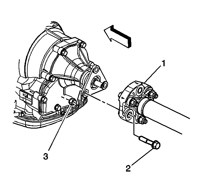
- Install the bolt securing the transmission fluid cooler pipe retainer to the transmission.
- Install the bolt securing the transmission fluid cooler pipes brace to the engine.
- Align the torque converter to flexplate/flywheel orientation marks made during the removal procedure.
- Repeat the following steps for all 3 torque converter bolts:
- Install the starter motor. Refer to Starter Motor Replacement.
- Install the air deflector front (1). Refer to Front Air Deflector Replacement.
- Connect the wiring harness clips to the transmission.
- Connect the transmission wiring harness connector (1) to the transmission by rotating the locking latch (2) clockwise.
- Install the propeller shaft coupler (1) to the transmission flange. Refer to Propeller Shaft Replacement.
- Place the transmission in the park position by rotating the shift shaft (2) fully counter clockwise.
- Connect the shift linkage (1) to the transmission.
- Install the transmission manual shift shaft retaining nut (3).
- Check the transmission fluid level (fill if necessary). Refer to Transmission Fluid Check.
- Adjust the shift control linkage. Refer to Shift Control Linkage Adjustment.
- Lower the vehicle.
- Connect the evap purge pipe.
- Install radiator retaining clips
- Install air intake ducting from engine
- Connect the negative battery cable. Refer to Battery Negative Cable Disconnection and Connection.
- The transmission control module must be programmed with the proper software/calibrations. Refer to Control Module References.
Important: The engine mounts must NOT bend or deflect from the vertical position, damage to the mount will occur.
Important: Ensure clearance is maintained between the
transmission and the following:
• The catalytic converters • The wiring harnesses • The cooler pipes • The propeller shaft
Notice: Refer to Fastener Notice in the Preface section.
Tighten
Tighten the bolts to 50 N·m (37 lb. ft).
Tighten
Tighten the studs to 10 N·m (89 lb. in).
Tighten
Tighten the front sub frame bolts to 160 N·m (118 lb. ft.).
Tighten
Tighten the transmission support to under body retaining
bolt to 63 N·m (46 lb ft).
Important: Replace the O-rings seals if cracked, cut, or distorted.
Tighten
Tighten the bolt to 25 N·m (18 lb. ft).
Tighten
Tighten the bolt to 50 N·m (37 lb. ft).
Important: Torque converter bolts are self locking and must be replaced with NEW torque converter bolts every time the bolts are removed.
| 16.1. | Rotate the harmonic balancer centre bolt clockwise ONLY, in order to align the torque converter bolt holes in the flexplate/flywheel with the starter motor opening in the engine block. |
| 16.2. | To aid in alignment of the torque converter to the flexplate/flywheel. Install all 3 NEW torque converter retaining bolts before fully tightening. |
Tighten
Tighten the bolts to 63 N·m (46 lb. ft).
Tighten
Tighten the nut to 15 N·m (11 lb. ft).
Transmission Final Test and Inspection
Complete the following procedure after the transmission is installed in the vehicle:
- With the ignition OFF or disconnected, turn the engine by hand several times. Listen for any unusual noises or evidence that any parts are binding.
- Start the engine and listen for abnormal sounds.
- While the engine continues to idle raise and support the vehicle. Refer to Lifting and Jacking the Vehicle.
- Inspect for fluid leaks while the engine is idling.
- Lower the vehicle.
- Perform a final inspection for the proper fluid level.
- Road test the vehicle.
