Rear Brake Caliper Replacement LHD
Removal Procedure
Tools Required
J 23738-A Hand Vacuum Pump.
- Inspect the fluid level in the brake master cylinder reservoir (1).
- Raise and support the vehicle. Refer to Lifting and Jacking the Vehicle.
- Remove the rear wheels. Refer to Tire and Wheel Removal and Installation.
- Install two wheel nuts (3) in reverse to opposite wheel studs to retain the brake disc to the hub.
- Install a large G-clamp over the body of the brake caliper (1).
- Tighten the G-clamp until the brake caliper piston bottoms out in the brake caliper bore.
- Remove the G-clamps from the brake caliper (1).
- Place a drain tray beneath the brake caliper assembly.
- Remove the brake hose to brake caliper banjo retaining bolt (5).
- Separate the brake hose to brake caliper banjo retaining bolt (5) from the brake hose (1).
- Remove and discard the two copper brake hose sealing washers (4). The copper brake hose sealing washers (4) may be stuck to the brake caliper (2) and/or the brake hose (1).
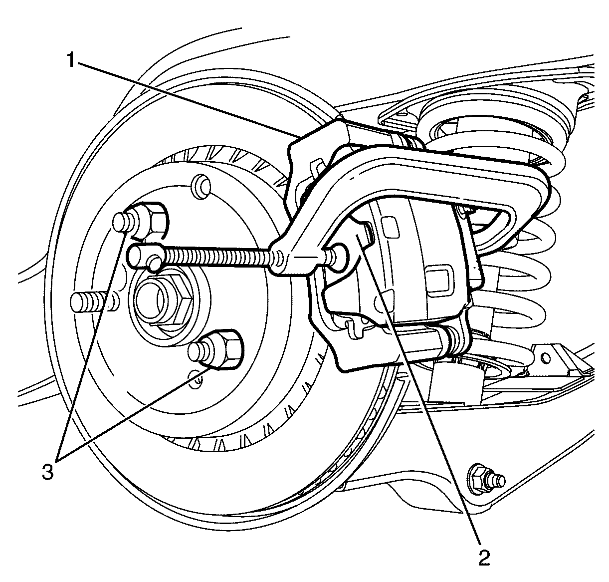
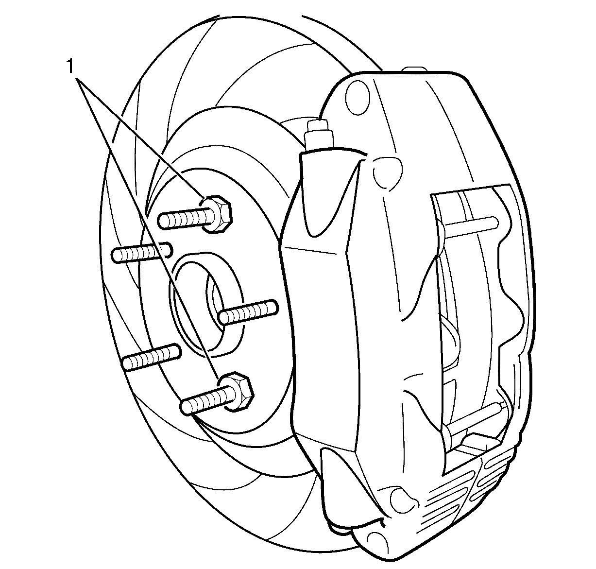
- Remove and discard the front brake caliper anchor plate to front steering knuckle retaining bolts (3).
- Remove the front brake caliper assembly (2) from the vehicle.
Caution: Refer to Safety Glasses Caution in the Preface section.
Caution: Refer to Vehicle Lifting Caution in the Preface section.
Caution: Refer to Brake Dust Caution in the Preface section.
Caution: Refer to Brake Fluid Caution in the Preface section.
Caution: Refer to Brake Fluid Irritant Caution in the Preface section.
Notice: Refer to Adding Fluid to the Brake System Notice in the Preface section.
Notice: Refer to Brake Fluid Effects on Paint and Electrical Components Notice in the Preface section.
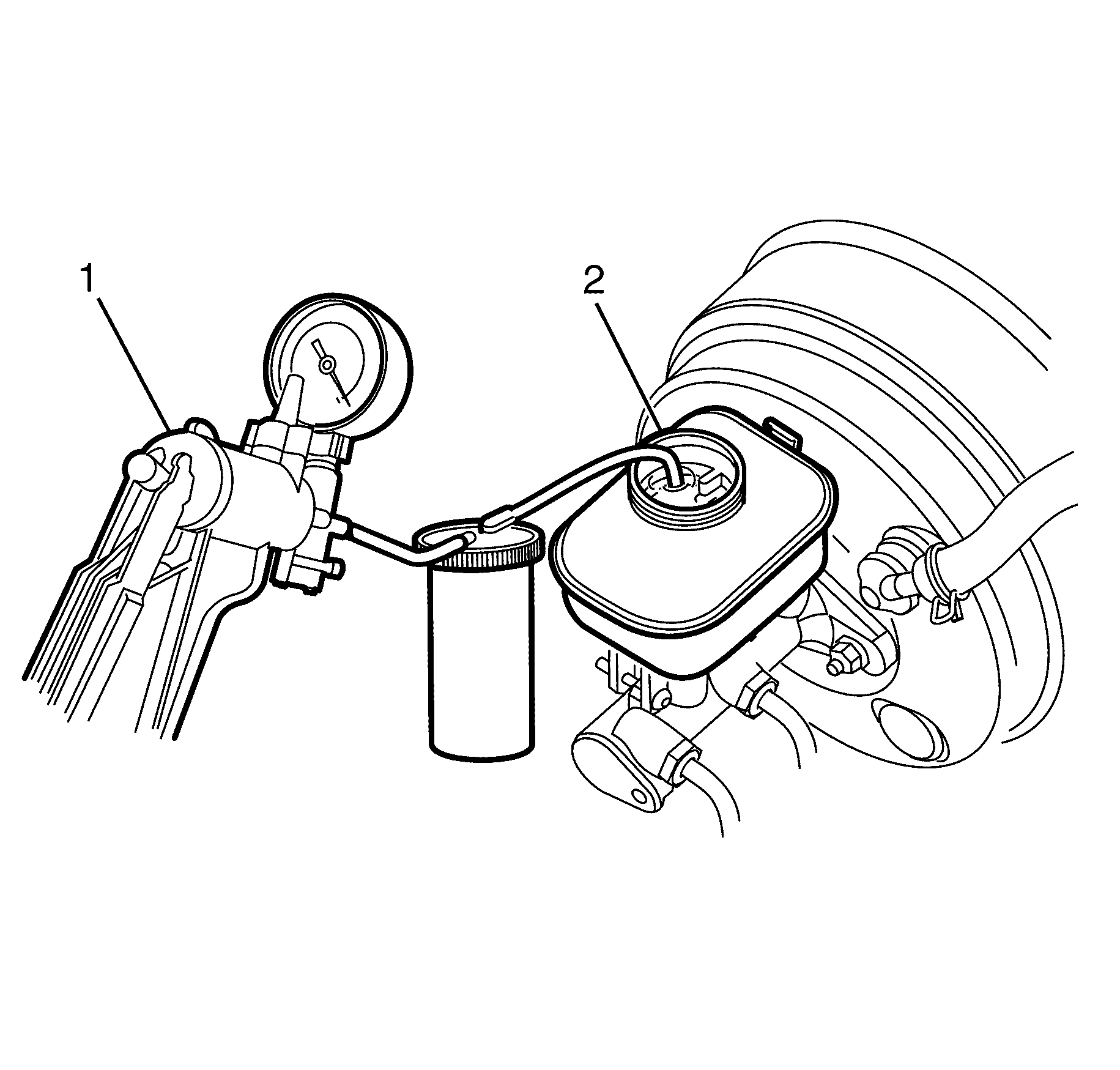
| • | If the brake fluid level is midway between the maximum [dash ] fill level and the minimum allowable level, no brake fluid needs to be removed from the master cylinder reservoir (2) before proceeding. |
| Important: DO NOT completely empty the master cylinder reservoir (2) or remove any brake lines otherwise complete bleeding of the braking system will be necessary. |
| Important: DO NOT re use the removed fluid. |
| • | If the brake fluid level is higher than midway between the maximum [dash ] fill level and the minimum allowable level, syphon the brake fluid to the midway point using a hand vacuum pump (1) before proceeding. |
Important: Position the ends of the G-clamp against the rear of the brake caliper (1) and against the outboard brake pad (2).
Important: Install a rubber cap or plug on the exposed brake hose end in order to prevent fluid loss and contamination.
Important: Copper brake hose sealing washers become work hardened due to the heat generated with brake applications and will not reseal. Install NEW copper brake hose sealing washers (4) whenever the brake hose to brake caliper banjo retaining bolt (5) is removed.
Important: Bolts with micro-encapsulated thread sealant must be discarded after removal.
Installation Procedure
- Clean the front brake caliper anchor plate mounting surfaces.
- Check the serviceability of the brake pads. Refer to Brake Pad Inspection
- Install the existing or NEW brake pads as required.
- Press the inner brake pad by using a suitable tool to make sure the brake caliper piston bottoms out in the brake caliper bore.
- Position the front brake caliper assembly over the brake disc.
- Install the NEW front brake caliper anchor plate to front steering knuckle retaining bolts (3).
- Install the front brake hose (1) to brake caliper banjo retaining bolt (5) and NEW copper sealing washers (4) to the brake caliper (2).
- Bleed the braking system. Refer to Hydraulic Brake System Bleeding.
- Remove the two wheel nuts retaining the brake disc to the hub.
- Install the rear wheels. Refer to Tire and Wheel Removal and Installation.
- Lower the vehicle to the ground.
- With the engine OFF, gradually apply the brake pedal to approximately 2/3 of its travel distance.
- Slowly release the brake pedal.
- Repeat steps 12 and 13 until a firm brake pedal is obtained. This will correctly seat the brake caliper pistons and brake pads.
- Fill the master cylinder reservoir to the correct level. Refer to Master Cylinder Reservoir Filling.
- Burnish (bed in) the brake pads and brake discs if required. Refer to Brake Pad and Rotor Burnishing.
Caution: Refer to Safety Glasses Caution in the Preface section.
Caution: Refer to Vehicle Lifting Caution in the Preface section.
Caution: Refer to Brake Dust Caution in the Preface section.
Caution: Refer to Brake Fluid Caution in the Preface section.
Caution: Refer to Brake Fluid Irritant Caution in the Preface section.
Notice: Refer to Adding Fluid to the Brake System Notice in the Preface section.
Notice: Refer to Brake Fluid Effects on Paint and Electrical Components Notice in the Preface section.
Important: The inner brake pads (4) are marked as left and right side only.
Notice: Refer to Fastener Notice in the Preface section.
Tighten
Tighten the bolt to 110 Nm (81 lb ft).
Notice: Make sure the brake hose is not twisted or kinked after installation. Damage to the hose could result.
Tighten
Tighten the banjo bolt to 35 Nm (26 lb ft).
Rear Brake Caliper Replacement CSV HSV VXR8
Removal Procedure
- Inspect the fluid level in the master cylinder reservoir.
- Raise and support the vehicle. Refer to Lifting and Jacking the Vehicle.
- Remove the front wheels. Refer to Tire and Wheel Removal and Installation.
- Install 2 wheel nuts (1), in reverse, to opposite wheel studs to retain the brake rotor to the rear wheel hub.
- Place a drain tray beneath the brake caliper assembly.
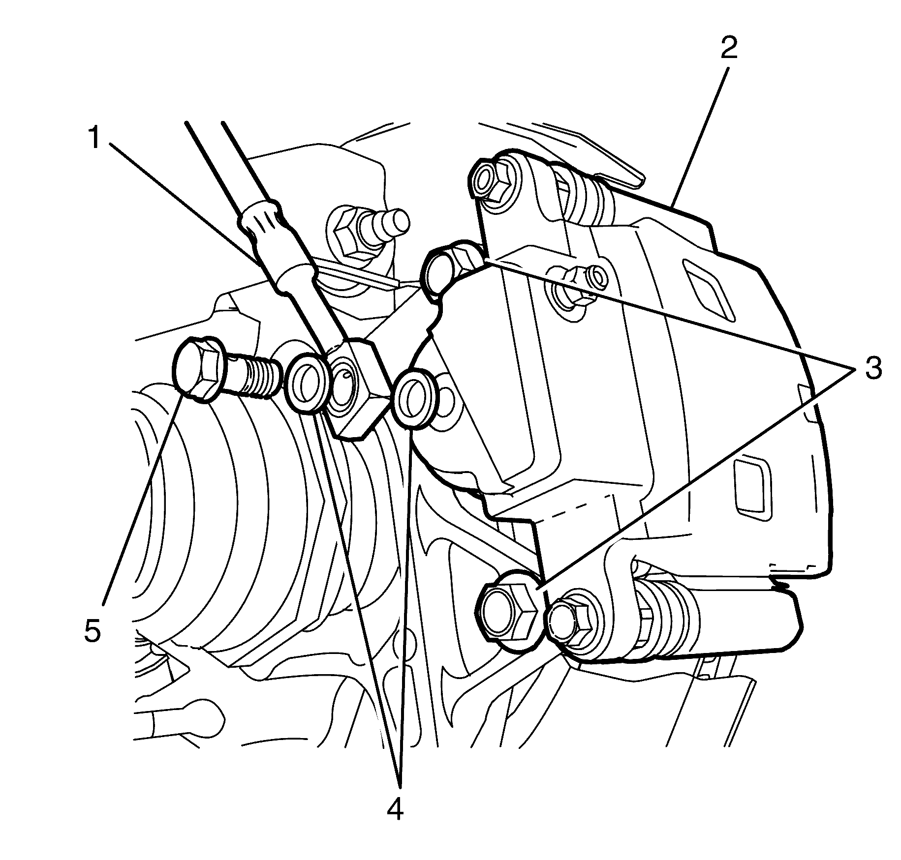
- Remove the brake hose to brake caliper banjo retaining bolt (1) and remove the brake hose (2) from the brake caliper (4).
- Gently warm the brake caliper to knuckle retaining bolts (3) with a heat gun to soften the micro encapsulated adhesive on the bolts.
- Remove and discard the brake caliper retaining bolts (3) from the brake caliper (4).
- Remove the brake caliper assembly (4).
Caution: Refer to Safety Glasses Caution in the Preface section.
Caution: Refer to Vehicle Lifting Caution in the Preface section.
Caution: Refer to Brake Dust Caution in the Preface section.
Caution: Refer to Brake Fluid Caution in the Preface section.
Caution: Refer to Brake Fluid Irritant Caution in the Preface section.
Notice: Refer to Adding Fluid to the Brake System Notice in the Preface section.
Notice: Refer to Brake Fluid Effects on Paint and Electrical Components Notice in the Preface section.
| • | If the brake fluid level is midway between the maximum fill level and the minimum allowable level, no brake fluid needs to be removed from the master cylinder reservoir before proceeding. |
| Important: DO NOT re-use the removed fluid. |
| • | If the brake fluid level is higher than midway between the maximum fill level and the minimum allowable level, syphon the brake fluid to the midway point using a hand vacuum pump before proceeding. |
Important: Install a rubber cap or plug on the exposed brake hose end in order to prevent fluid loss and contamination.
Important: Copper brake hose sealing washers become work hardened due to the heat generated with brake applications and will not reseal. Install NEW copper brake hose sealing washers whenever the brake hose to brake caliper banjo bolt is removed.
Important: To facilitate removal of the brake caliper, the reversed wheel nuts holding the brake rotor in position will need to be loosened and the brake pads fully pushed back against the pistons within the caliper.
Discard the washers.
Installation Procedure
- Clean the brake caliper mounting surfaces and brake caliper mounting threads using brake clean and a thread chaser (M12x1.5) to remove the remaining adhesive and avoid thread damage during bolt installation.
- Check the serviceability of the brake pads. Refer to Brake Pad Inspection.
- Install the existing or NEW brake pads if required. Refer to Rear Disc Brake Pads Replacement.
- Position the brake caliper over the brake rotor. The brake rotor may need to be moved forward to allow clearance for placement of the brake caliper.
- Install the NEW brake caliper to knuckle retaining bolts (3).
- Install the brake hose (2), the brake hose to brake caliper banjo bolt (1) and NEW copper brake hose sealing washers to the brake caliper (4).
- Bleed the braking system. Refer to Hydraulic Brake System Bleeding.
- Remove the wheel nuts (1) retaining the brake rotor to the rear wheel hub.
- Install the rear wheels. Refer to Tire and Wheel Removal and Installation.
- Lower the vehicle to the ground.
- With the Ignition Off, gradually apply the brake pedal to approximately 2/3 of its travel distance.
- Slowly release the brake pedal.
- Repeat steps 12 and 13 until a firm brake pedal application is obtained. This will correctly seat the brake caliper pistons and brake pads.
- Fill the master cylinder reservoir to the correct level. Refer to Master Cylinder Reservoir Filling.
- Burnish (bed in) the brake pads and brake rotors if required. Refer to Brake Pad and Rotor Burnishing.
Notice: Refer to Brake Fluid Effects on Paint and Electrical Components Notice in the Preface section.
Notice: When adding fluid to the brake master cylinder reservoir, use only Holden specification number HN 1796 (Super DOT 4/DOT 4 Plus) brake fluid from a clean, sealed brake fluid container. The use of any type of fluid other than the recommended type of brake fluid may cause contamination which may result in damage to the internal rubber seals and/or rubber linings of hydraulic brake system components.
Important: Each inner and outer brake pad should be installed and removed in its original position. To decrease the risk of installing the brake pads in the wrong position, index the brake pads according to their installed position. Failure to install the brake pads in their correct position will cause the brake pads not to seat correctly in the brake caliper.
Notice: Refer to Fastener Notice in the Preface section.
Important: Under no circumstances is an impact wrench to be used on the following bolts.
Tighten
Tighten the brake caliper to knuckle retaining bolts
to 110 Nm (81 lb ft).
Notice: Make sure the brake hose is not twisted or kinked after installation. Damage to the hose could result.
Important: Install NEW copper brake hose sealing washers.
Tighten
Tighten the bolt to 33 Nm (25 lb ft).
Rear Brake Caliper Replacement RHD
Removal Procedure
Tools Required
J 23738-A Hand Vacuum Pump.
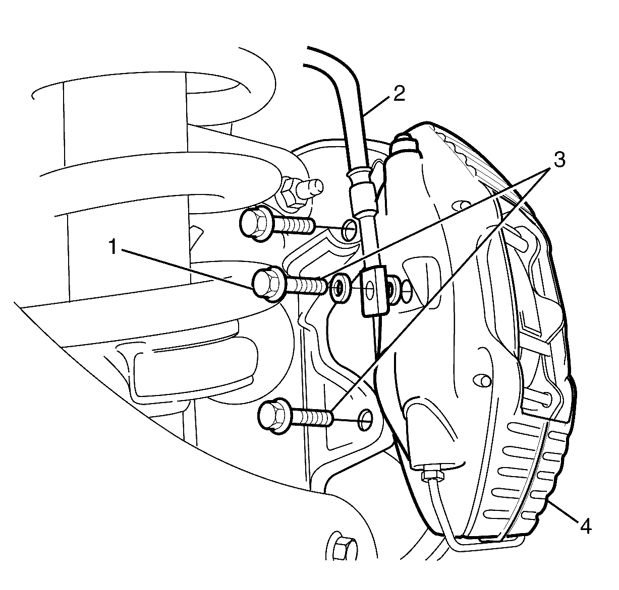
- Inspect the fluid level in the brake master cylinder reservoir (2).
- Raise and support the vehicle. Refer to Lifting and Jacking the Vehicle .
- Remove the front wheels. Refer to Tire and Wheel Removal and Installation .
- Install two wheel nuts (3) in reverse to opposite wheel studs to retain the brake disc to the hub.
- Install a large G-clamp over the body of the brake caliper (1).
- Tighten the G-clamp until the brake caliper piston bottoms out in the brake caliper bore.
- Remove the G-clamps from the brake caliper (1).
- Place a drain tray beneath the brake caliper assembly.
- Remove the brake hose to brake caliper banjo retaining bolt (5).
- Separate the brake hose to brake caliper banjo retaining bolt (5) from the brake hose (1).
- Remove the two copper brake hose sealing washers (4). The copper brake hose sealing washers (4) may be stuck to the brake caliper (2) and/or the brake hose (1).
- Remove the brake caliper anchor plate to knuckle retaining bolts (3).
- Remove the brake caliper assembly (2) from the vehicle.
Caution: Refer to Safety Glasses Caution in the Preface section.
Caution: Refer to Vehicle Lifting Caution in the Preface section.
Caution: Refer to Brake Dust Caution in the Preface section.
Caution: Refer to Brake Fluid Caution in the Preface section.
Caution: Refer to Brake Fluid Irritant Caution in the Preface section.
Notice: Refer to Adding Fluid to the Brake System Notice in the Preface section.
Notice: Refer to Brake Fluid Effects on Paint and Electrical Components Notice in the Preface section.
| • | If the brake fluid level is midway between the maximum [dash ] fill level and the minimum allowable level, no brake fluid needs to be removed from the master cylinder reservoir (2) before proceeding. |
| Important: DO NOT completely empty the master cylinder reservoir (2) or remove any brake lines otherwise complete bleeding of the braking system will be necessary. |
| Important: DO NOT re use the removed fluid. |
| • | If the brake fluid level is higher than midway between the maximum [dash ] fill level and the minimum allowable level, using a hand vacuum pump (1) syphon the brake fluid to the midway point before proceeding. |
Important: Position the ends of the G-clamp against the rear of the brake caliper (1) and against the outboard brake pad (2).
Important: Install a rubber cap or plug on the exposed brake hose end in order to prevent fluid loss and contamination.
Important: Copper brake hose sealing washers become work hardened due to the heat generated with brake applications and will not reseal. Install NEW copper brake hose sealing washers (4) whenever the brake hose to brake caliper banjo retaining bolt (5) is removed.
Discard the sealing washers.
Important: Bolts with micro-encapsulated thread sealant must be discarded after removal.
Important: Make sure all the bolt holes are thoroughly cleaned and all micro-encapsulated thread sealant is removed.
Discard the bolts.
Clean the bolt holes.
Installation Procedure
- Clean the brake caliper anchor plate to steering knuckle mounting surfaces.
- Check the serviceability of the brake pads. Refer to Brake Pad Inspection .
- Install the existing or NEW brake pads as required.
- Press the inner brake pad by using a suitable tool to make sure the brake caliper piston bottoms out in the brake caliper bore.
- Position the brake caliper assembly over the brake disc.
- Install the NEW brake caliper anchor plate to knuckle retaining bolts (3).
- Install the brake hose (1) to brake caliper banjo retaining bolt (5) and NEW copper sealing washers (4) to the brake caliper (2).
- Bleed the braking system. Refer to Hydraulic Brake System Bleeding .
- Remove the wheel nuts retaining the brake disc to the hub.
- Install the rear wheels. Refer to Tire and Wheel Removal and Installation .
- Lower the vehicle to the ground.
- With the engine OFF, gradually apply the brake pedal to approximately 2/3 of its travel distance.
- Slowly release the brake pedal.
- Repeat steps 12 and 13 until a firm brake pedal is obtained. This will correctly seat the brake caliper pistons and brake pads.
- Fill the master cylinder reservoir to the correct level. Refer to Master Cylinder Reservoir Filling .
- Burnish (bed in) the brake pads and brake discs if required. Refer to Brake Pad and Rotor Burnishing .
Caution: Refer to Safety Glasses Caution in the Preface section.
Caution: Refer to Vehicle Lifting Caution in the Preface section.
Caution: Refer to Brake Dust Caution in the Preface section.
Caution: Refer to Brake Fluid Caution in the Preface section.
Caution: Refer to Brake Fluid Irritant Caution in the Preface section.
Notice: Refer to Adding Fluid to the Brake System Notice in the Preface section.
Notice: Refer to Brake Fluid Effects on Paint and Electrical Components Notice in the Preface section.
Important: The inner brake pads are marked as left and right side only.
Notice: Refer to Fastener Notice in the Preface section.
Tighten
Tighten the bolt to 110 Nm (81 lb ft).
Notice: Make sure the brake hose is not twisted or kinked after installation. Damage to the hose could result.
Tighten
Tighten the banjo bolt to 35 Nm (26 lb ft).
