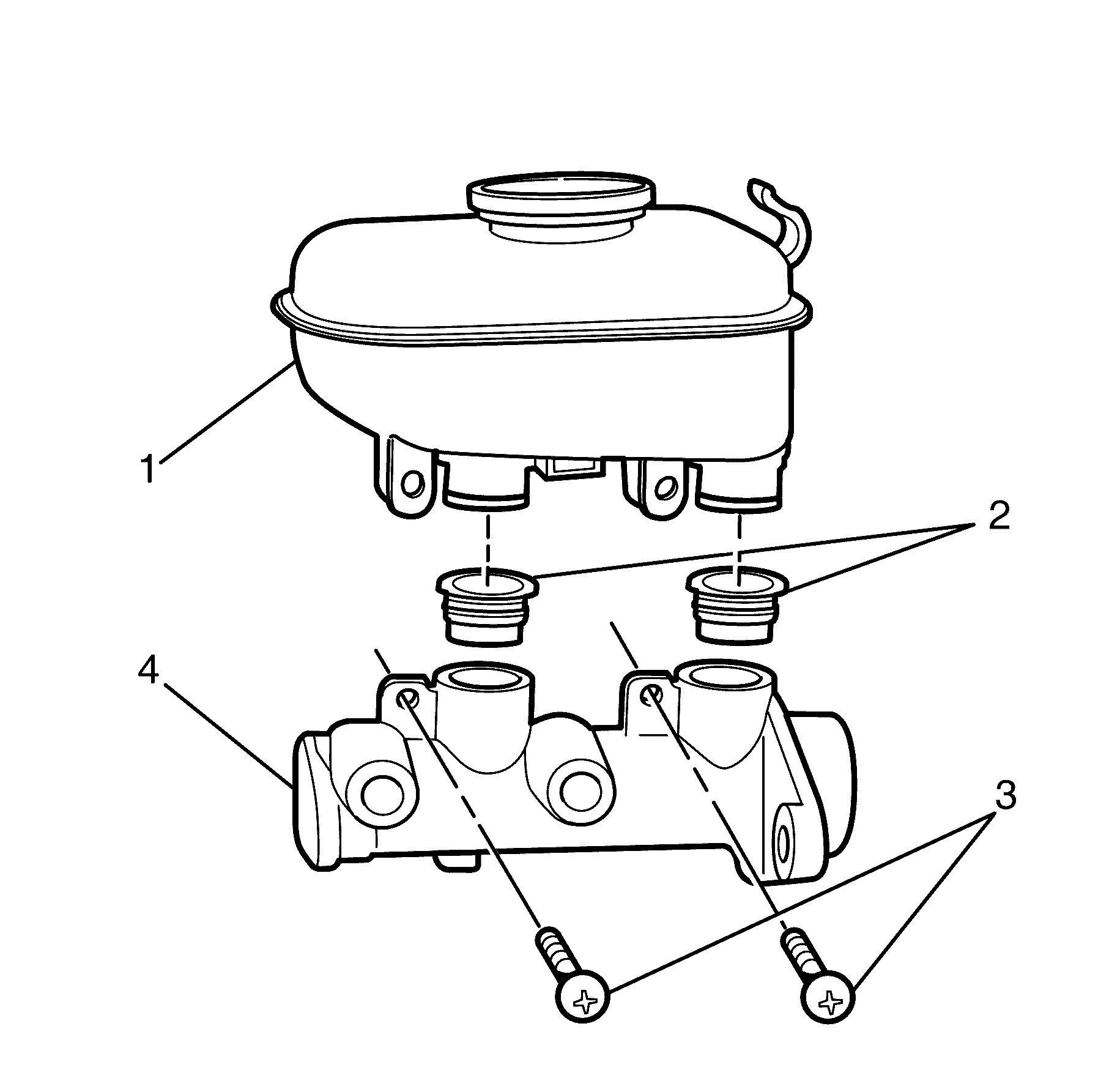
Master Cylinder Reservoir Replacement LHD
Removal Procedure
- Disconnect the battery ground cable. Refer to Battery Negative Cable Disconnection and Connection.
- Apply the park brake and chock the wheels.
- Deplete the vacuum brake booster power reserve.
- Remove the master cylinder. Refer to Master Cylinder Replacement.
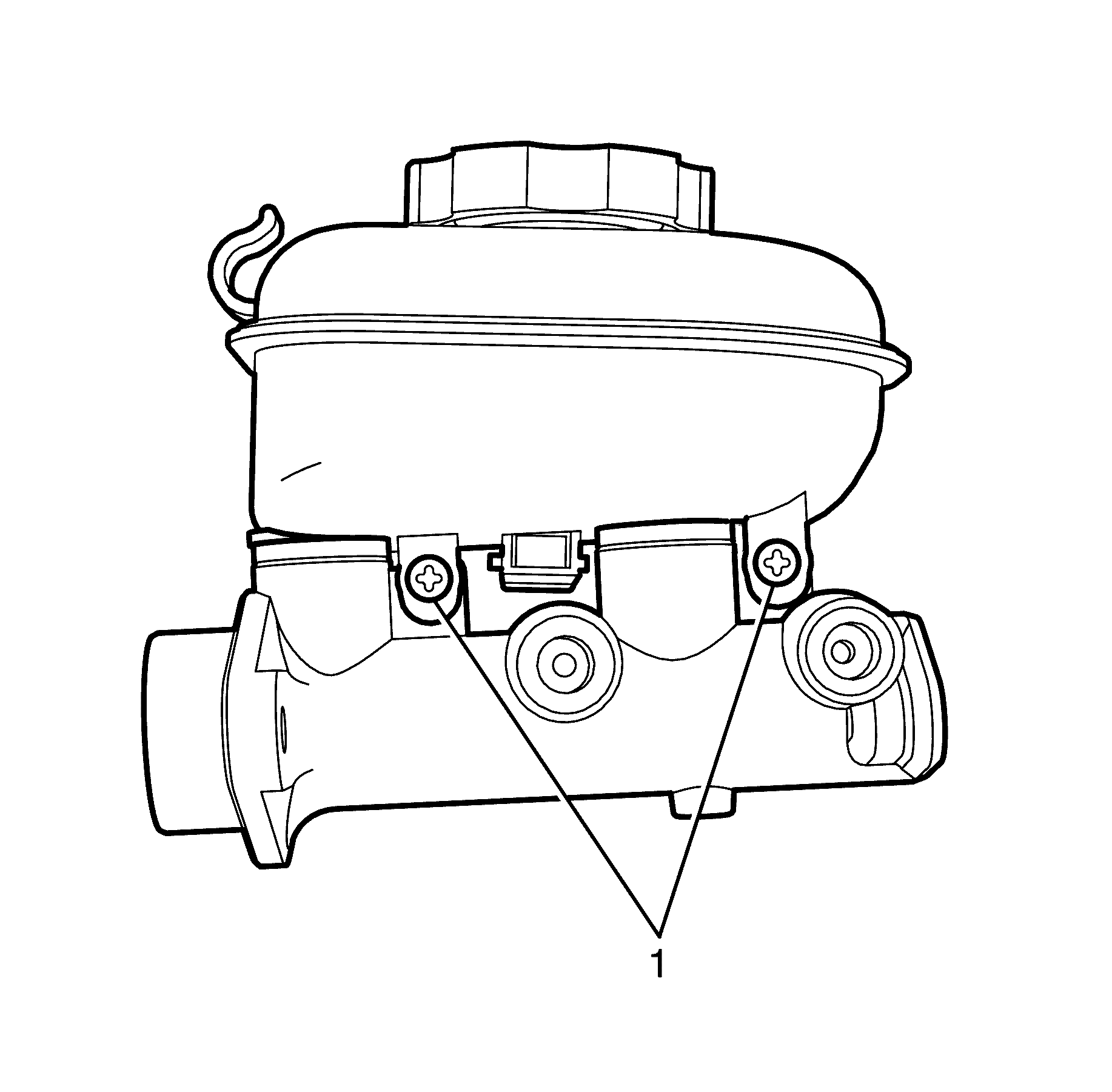
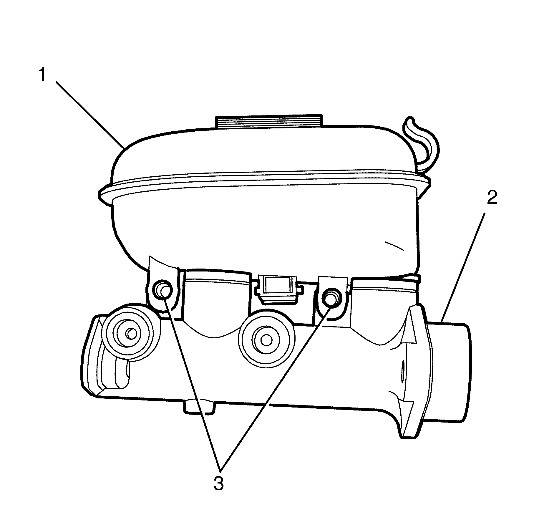
- Remove the master cylinder reservoir to master cylinder retaining screws (4).
- Remove the master cylinder reservoir (2) from the master cylinder (3).
- Remove the two master cylinder reservoir seals (1) from the master cylinder (3).
Caution: Refer to Battery Disconnect Caution in the Preface section.
Caution: Refer to Brake Fluid Caution in the Preface section.
Caution: Refer to Brake Fluid Irritant Caution in the Preface section.
Notice: Refer to Adding Fluid to the Brake System Notice in the Preface section.
Notice: Refer to Brake Fluid Effects on Paint and Electrical Components Notice in the Preface section.
Important: With the ignition OFF and the brakes cool, apply the brakes three to five times, or until the brake pedal effort increases significantly, in order to deplete the vacuum brake booster power reserve.
Important: To remove the master cylinder reservoir (2) grasp the master cylinder (3) then pull up on the master cylinder reservoir (2).
Important: Master cylinder reservoir seals (1) are single use only components and will not reseal. Install NEW master cylinder reservoir seals (1) whenever the master cylinder reservoir (2) is removed from the master cylinder (3).
Discard the two master cylinder reservoir seals (1).
Installation Procedure
- Install the NEW master cylinder reservoir seals to the master cylinder body.
- Install the master cylinder reservoir (2) to the master cylinder body (1).
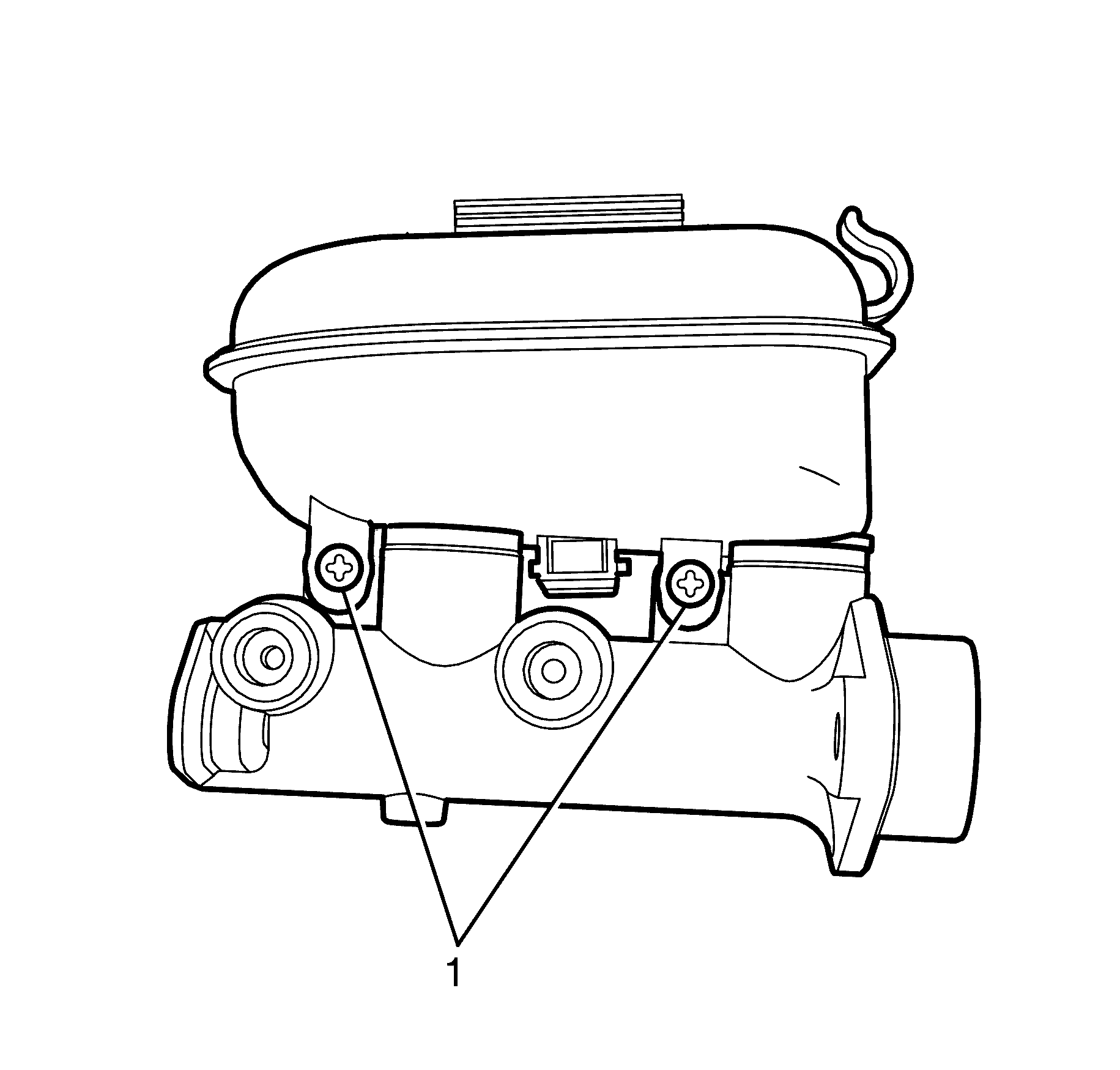
- Install the master cylinder reservoir to master cylinder retaining screws (1).
- Install the master cylinder. Refer to Master Cylinder Replacement.
- Connect the battery ground cable. Refer to Battery Negative Cable Disconnection and Connection.
Caution: Refer to Brake Fluid Caution in the Preface section.
Caution: Refer to Brake Fluid Irritant Caution in the Preface section.
Notice: Refer to Adding Fluid to the Brake System Notice in the Preface section.
Notice: Refer to Brake Fluid Effects on Paint and Electrical Components Notice in the Preface section.
Important: Lubricate the NEW master cylinder reservoir seals and the outer surface of the NEW master cylinder reservoir to housing barrels with brake fluid conforming to specification, from a clean, sealed brake fluid container in order to prevent tearing on installation. Refer to Brake System Specifications for correct brake fluid specification.
Make sure they are fully seated.
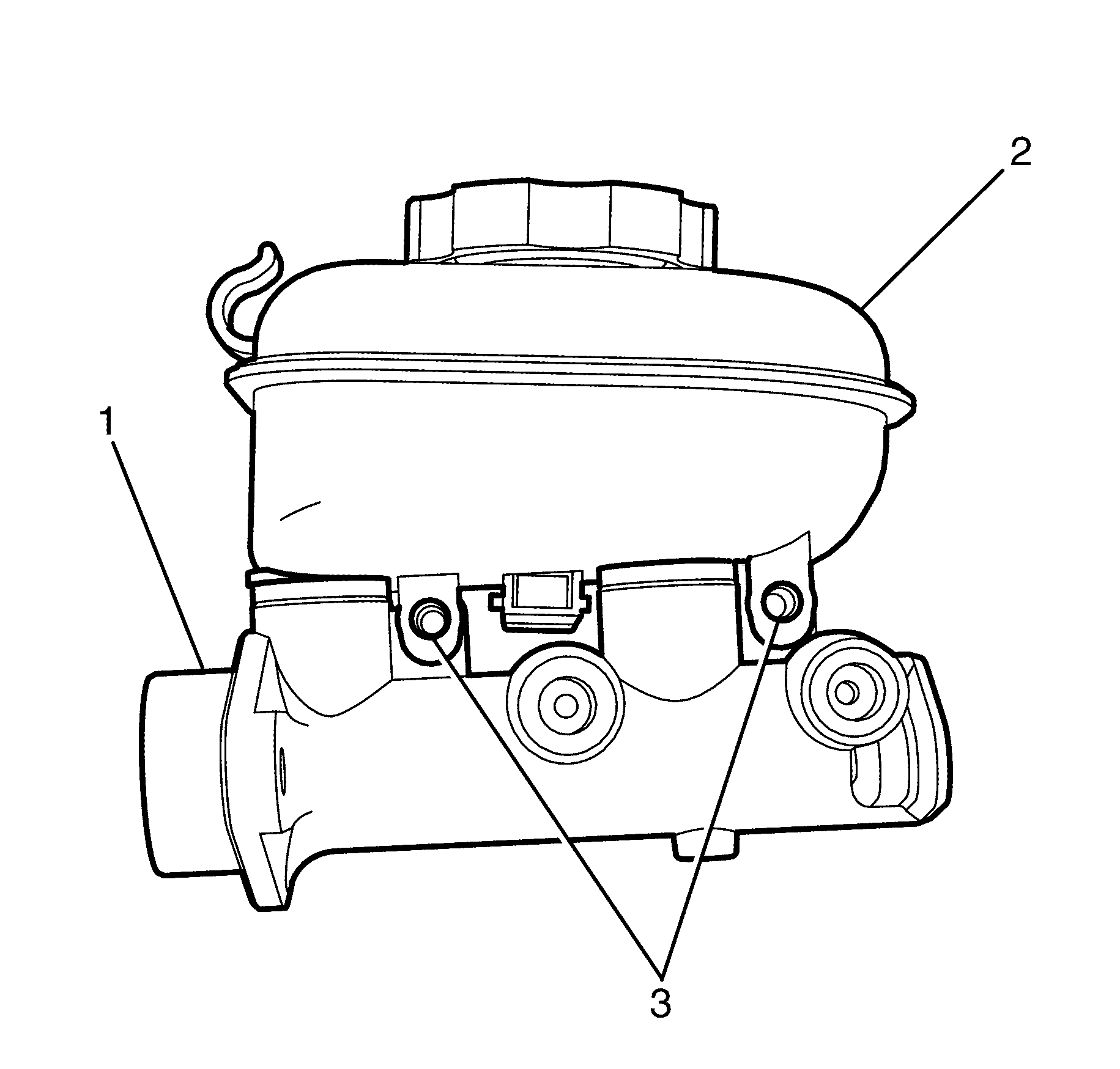
Important: Press down on the master cylinder reservoir (2) until the master cylinder reservoir to master cylinder retaining screw holes (3) the master cylinder body (1) are aligned.
Notice: Refer to Fastener Notice in the Preface section.
Tighten
Tighten the screws to 2.0 N·m (18 lb in).
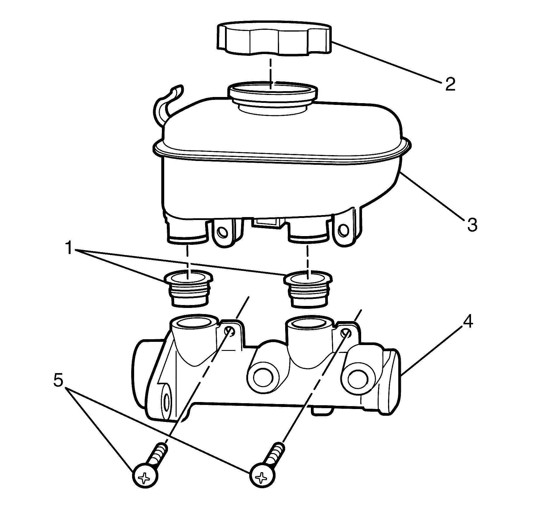
Master Cylinder Reservoir Replacement RHD
Removal Procedure
- Disconnect the battery ground cable. Refer to Battery Negative Cable Disconnection and Connection.
- Apply the park brake and chock the wheels.
- Deplete the vacuum brake booster power reserve.
- Remove the master cylinder. Refer to Master Cylinder Replacement.
- Clean the master cylinder reservoir (1), and master cylinder (5).
- Remove the master cylinder reservoir cap (2).
- Remove the master cylinder reservoir to master cylinder retaining screws (4).
- Remove the master cylinder reservoir (1) from the master cylinder (5).
- Remove the two master cylinder reservoir seals (3) from the master cylinder (5).
Caution: Refer to Battery Disconnect Caution in the Preface section.
Caution: Refer to Brake Fluid Caution in the Preface section.
Caution: Refer to Brake Fluid Irritant Caution in the Preface section.
Notice: Refer to Adding Fluid to the Brake System Notice in the Preface section.
Notice: Refer to Brake Fluid Effects on Paint and Electrical Components Notice in the Preface section.
Important: With the ignition OFF and the brakes cool, apply the brakes three to five times, or until the brake pedal effort increases significantly, in order to deplete the vacuum brake booster power reserve.
Important: To remove the master cylinder reservoir (1) grasp the master cylinder (5) then pull up on the master cylinder reservoir (1).
Important: Master cylinder reservoir seals (3) are single use only components and will not reseal. Install NEW master cylinder reservoir seals (3) whenever the master cylinder reservoir (1) is removed from the master cylinder (5).
Discard the two master cylinder reservoir seals (3).
Installation Procedure
- Install the NEW master cylinder reservoir seals to the master cylinder body.
- Install the master cylinder reservoir (1) to the master cylinder body (2).
- Install the master cylinder reservoir to master cylinder retaining screws (1).
- Install the master cylinder. Refer to Master Cylinder Replacement.
- Connect the battery ground cable. Refer to Battery Negative Cable Disconnection and Connection.
Caution: Refer to Brake Fluid Caution in the Preface section.
Caution: Refer to Brake Fluid Irritant Caution in the Preface section.
Notice: Refer to Adding Fluid to the Brake System Notice in the Preface section.
Notice: Refer to Brake Fluid Effects on Paint and Electrical Components Notice in the Preface section.
Important: Lubricate the NEW master cylinder reservoir seals and the outer surface of the NEW master cylinder reservoir to housing barrels with brake fluid conforming to specification, from a clean, sealed brake fluid container in order to prevent tearing on installation. Refer to Brake System Specifications for correct brake fluid specification.
Make sure they are fully seated.
Important: Press down on the master cylinder reservoir (1) until the master cylinder reservoir to master cylinder retaining screw holes in the master cylinder body (3) are aligned.
Notice: Refer to Fastener Notice in the Preface section.
Tighten
Tighten the screws to 2.5 N·m (22 lb in).
