Adjust Link Replacement LWB SWB
Removal Procedure - Up to 09 Oct 2007
- Raise and support the vehicle. Refer to Lifting and Jacking the Vehicle.
- Remove the rear wheel. Refer to Tire and Wheel Removal and Installation.
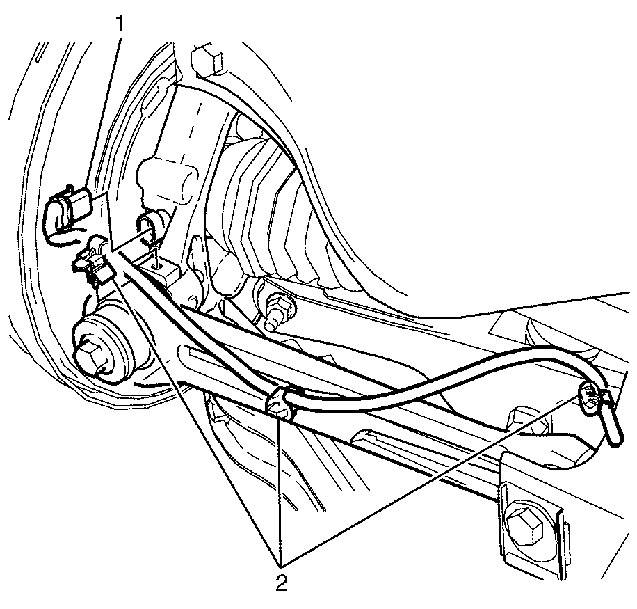
- Disconnect the wheel speed sensor wiring harness mounting clip (1) from the I-Link.
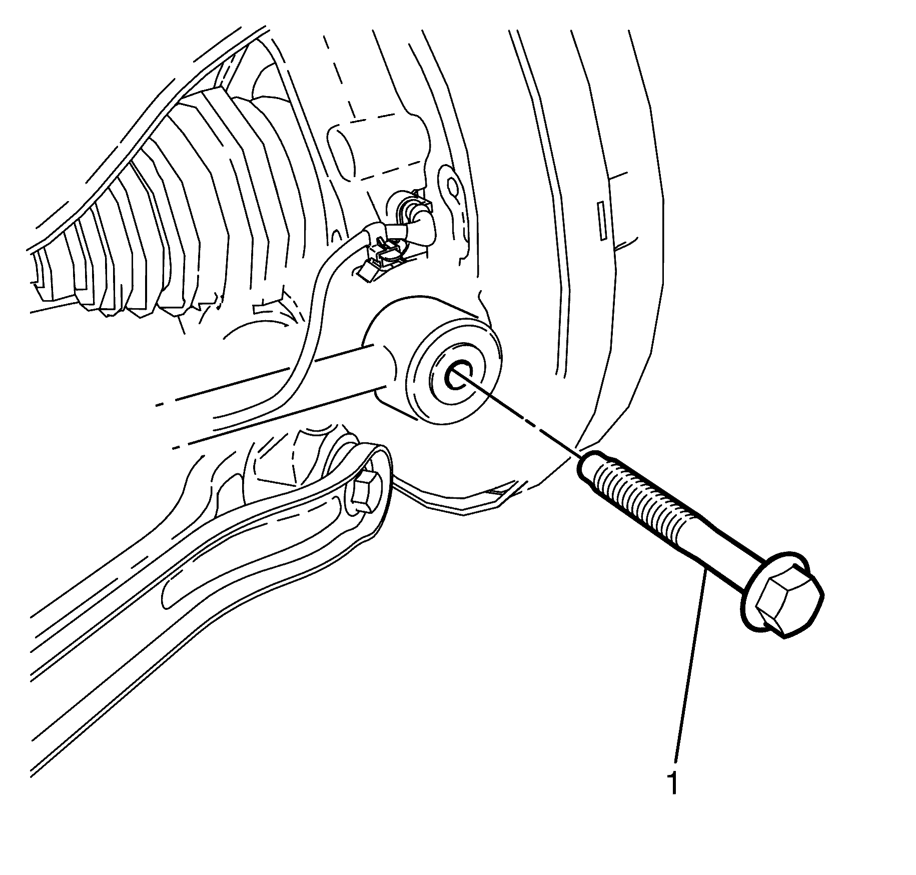
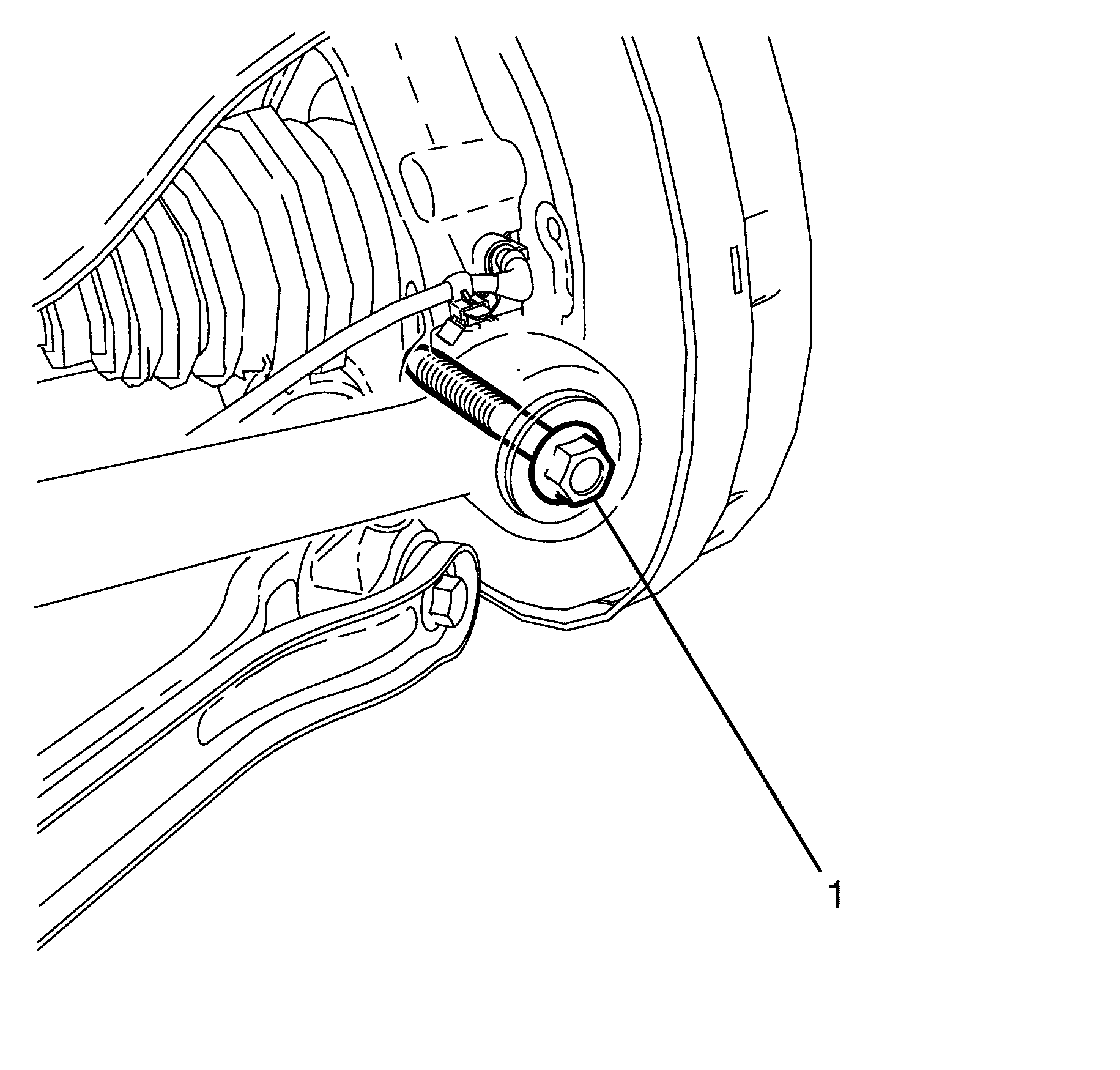
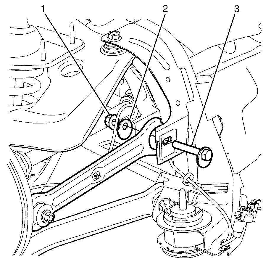
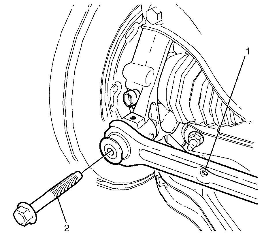
- Remove the I-Link to the knuckle retaining bolt (1) and washer (2).
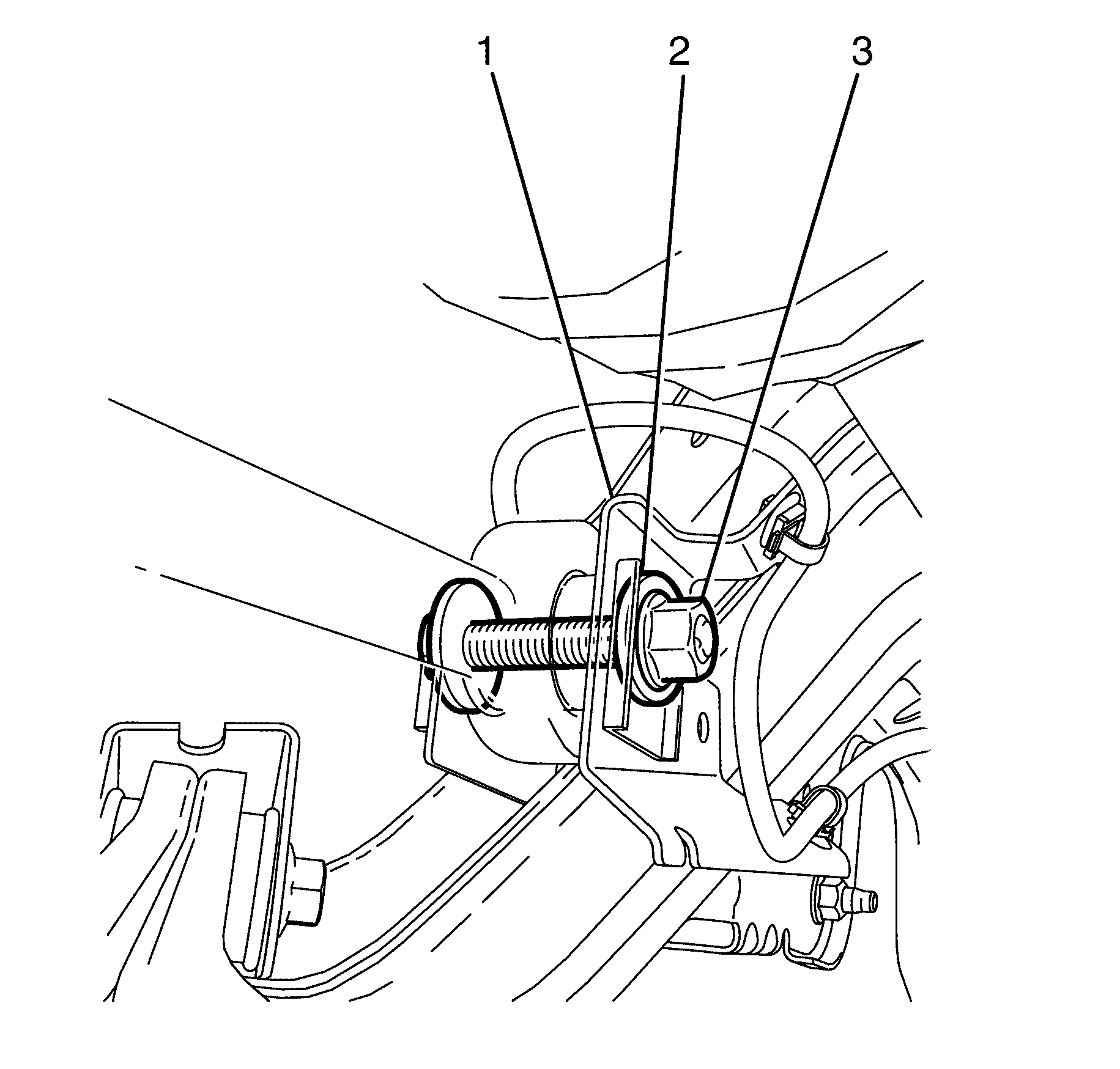
- Remove the I-Link to subframe retaining bolt, washer (2) and nut (3).
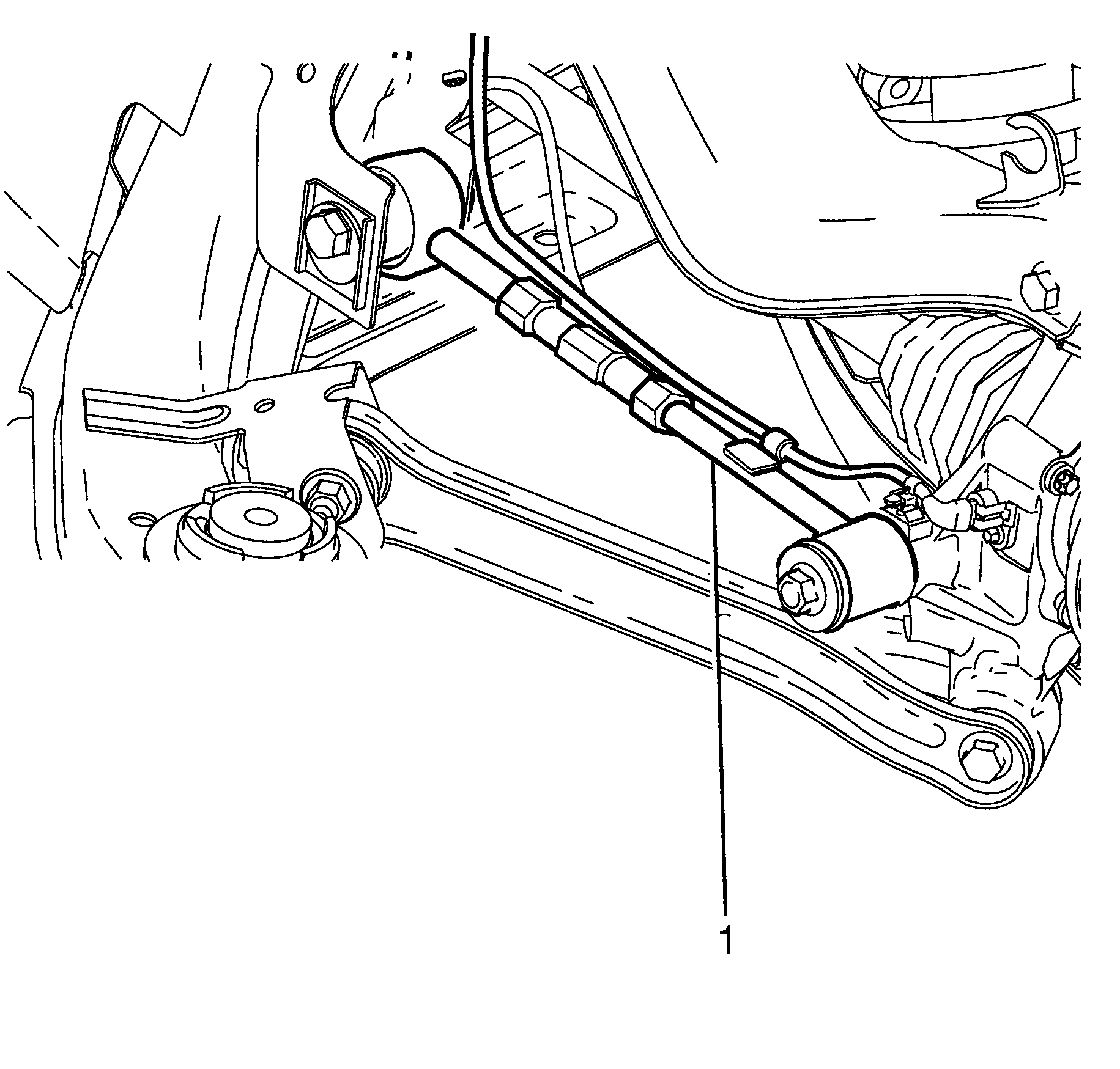
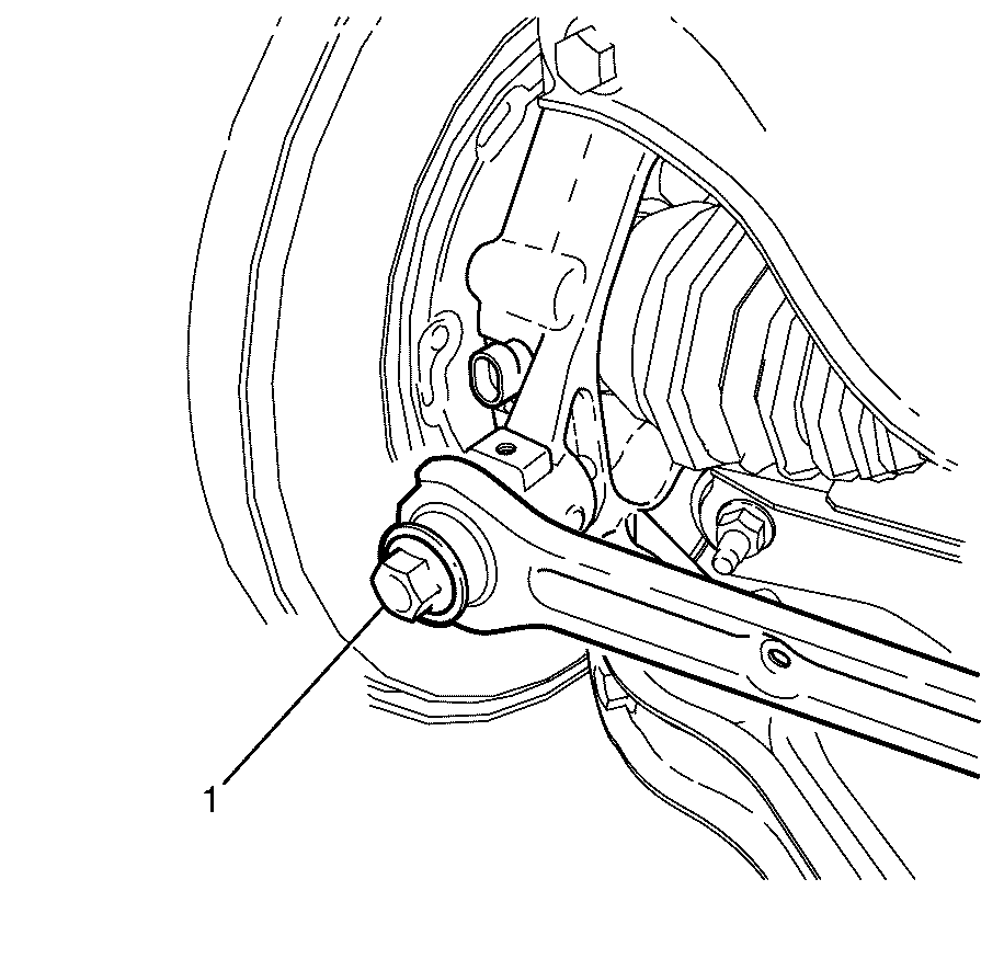
- Remove the I-Link from the subframe (1).
- Inspect all parts for wear and damage.
Caution: Refer to Safety Glasses Caution in the Preface section.
Caution: Refer to Vehicle Lifting Caution in the Preface section.
Important: Prevailing torque nuts must be discarded after removal.
Discard the nut.
Installation Procedure - Up to 09 Oct 2007
- Install the I-Link into the subframe (1).
- Install the I-Link to subframe retaining bolt, washer (2) and NEW nut (3).
- Install the I-Link to knuckle retaining bolt (1).
- Install the rear wheel. Refer to Tire and Wheel Removal and Installation.
- Remove the safety stands.
- Lower the vehicle to the ground.
- Bounce the vehicle several times to settle the suspension.
- Tighten the I-Link to subframe (1) retaining bolt, washer (2) and NEW nut (3).
- Tighten the I-Link to knuckle retaining bolt (1).
- Check the wheel alignment of the vehicle. Refer to Wheel Alignment Measurement.
- Correct the wheel alignment of the vehicle, if necessary. Refer to Rear Camber Adjustment , and Rear Toe Adjustment.
Important: The I-Link to subframe retaining bolt and nut must not to be fully tightened at this stage.
Do not fully tighten at this stage.
Important: The I-Link to knuckle retaining bolt (1) must not to be fully tightened at this stage.
Do not fully tighten at this stage.
Notice: Refer to Fastener Notice in the Preface section.
Tighten
Tighten the bolt and nut to 175 N·m
(129 lb ft).
Tighten
Tighten the bolt to 140 N·m (103 lb ft).
Removal Procedure - After 09 Oct 2007
- Raise and support the vehicle. Refer to Lifting and Jacking the Vehicle.
- Remove the rear wheel. Refer to Tire and Wheel Removal and Installation.
- Disconnect the wheel speed sensor electrical connector (1).
- Detach the wheel speed sensor wiring harness retainers (2).
- Remove the I-Link to subframe retaining nut (1), eccentric washer (2) and retaining bolt (3).
- Discard the I-Link to subframe retaining nut (1).
- Remove the I-Link to knuckle retaining bolt (2).
- Remove the I-Link from the subframe (1).
Caution: Refer to Safety Glasses Caution in the Preface section.
Caution: Refer to Vehicle Lifting Caution in the Preface section.
Important: The later type stamped adjust links can be used to replace the earlier turn buckle type adjust links. However they must be replaced as a matched pair.
Important: Mark the I-Link to subframe retaining bolt (3) in relation to the subframe before removing the I-Link to subframe retaining nut (1).
Installation Procedure - After 09 Oct 2007
- Install the NEW I-Link (1)
- Install the I-Link to knuckle retaining bolt (2).
- Loosen the bolt by 90 degrees
- Install the I-Link to subframe retaining bolt (3), washer (2) and NEW nut (1).
- Using a suitable tool, align the previously made aligning mark on the I-Link to subframe retaining bolt (3) to the corresponding rear subframe mark.
- Using a suitable tool, hold the I-Link to subframe retaining bolt (3) in the correct position and tighten the NEW nut (1).
- Loosen the nut by 90 degrees.
- Install the rear wheel. Refer to Tire and Wheel Removal and Installation.
- Lower the vehicle. Refer to Lifting and Jacking the Vehicle.
- Settle the suspension.
- Tighten the I-Link to knuckle retaining bolt (1).
- Using a suitable tool, align the previously made aligning marks on the I-Link to subframe retaining bolt (1) and hold in position.
- Tighten the I-Link to subframe retaining nut (2).
- Connect the wheel speed sensor electrical connector (1).
- Attach the wheel speed sensor wiring harness retainers (2).
- Check the vehicle rear wheel alignment and adjust if necessary. Refer to Wheel Alignment Specifications.
- Correct the wheel alignment of the vehicle, if necessary. Refer to Rear Camber Adjustment Rear Camber Adjustment, and Rear Toe Adjustment Rear Toe Adjustment.
Important: The I-Link to knuckle retaining bolt (1) is not to be fully tightened at this stage.
Tighten
Tighten the bolt to 20 N·m (15 lb ft).
Important: The I-Link to subframe retaining bolt and nut must not to be fully tightened at this stage.
Tighten
Tighten the nut to 20 N·m (15 lb ft).
Caution: Refer to Safety Glasses Caution in the Preface section.
Caution: Refer to Vehicle Lifting Caution in the Preface section.
Notice: Refer to Fastener Notice in the Preface section.
Important: The weight of the vehicle must be on a level surface and on all four wheels before fully tightening the nut.
Important: The suggested method to settle the rear suspension is with the wheels on the ground, open rear compartment lid and support the lid with a suitable brace. Using your hands press down hard on the rear compartment floor and release a number of times.
Tighten
Tighten the bolt to 140 N·m (103 lb ft).

Tighten
Tighten the nut to 175 N·m (129 lb ft).
Adjust Link Replacement CSV HSV VXR8
Removal Procedure
- Raise and support the vehicle. Refer to Lifting and Jacking the Vehicle.
- Remove the rear wheel. Refer to Tire and Wheel Removal and Installation.
- Disconnect the wheel speed sensor wiring harness mounting clip (1) from the I-Link.
- Remove the I-Link to the knuckle retaining bolt (1) and washer (2).
- Remove the I-Link to subframe retaining bolt, washer (2) and nut (3).
- Remove the I-Link from the subframe (1).
- Inspect all parts for wear and damage.
Caution: Refer to Safety Glasses Caution in the Preface section.
Caution: Refer to Vehicle Lifting Caution in the Preface section.
Important: Prevailing torque nuts must be discarded after removal.
Discard the nut.
Installation Procedure
- Install the I-Link into the subframe (1).
- Install the I-Link to subframe retaining bolt, washer (2) and NEW nut (3).
- Install the I-Link to knuckle retaining bolt (1).
- Install the rear wheel. Refer to Tire and Wheel Removal and Installation.
- Remove the safety stands.
- Lower the vehicle to the ground.
- Bounce the vehicle several times to settle the suspension.
- Tighten the I-Link to subframe (1) retaining bolt, washer (2) and NEW nut (3).
- Tighten the I-Link to knuckle retaining bolt (1).
- Check the wheel alignment of the vehicle. Refer to Wheel Alignment Measurement.
- Correct the wheel alignment of the vehicle, if necessary. Refer to Rear Camber Adjustment, and Rear Toe Adjustment.
Important: The I-Link to subframe retaining bolt and nut must not to be fully tightened at this stage.
Do not fully tighten at this stage.
Important: The I-Link to knuckle retaining bolt (1) must not to be fully tightened at this stage.
Do not fully tighten at this stage.
Notice: Refer to Fastener Notice in the Preface section.
Tighten
Tighten the bolt and nut to 175 N·m
(129 lb ft).
Tighten
Tighten the bolt to 140 N·m (103 lb ft).
