Oil Pan Replacement LHD
Removal Procedure
- Disconnect the battery ground cable. Refer to Battery Negative Cable Disconnection and Connection.
- Raise and support the vehicle. Refer to Lifting and Jacking the Vehicle.
- Remove the air deflector. Refer to Front Air Deflector Replacement.
- Drain the engine oil and remove the oil filter. Refer to Engine Oil and Oil Filter Replacement.
- Remove the engine splash shield. Refer to Engine Splash Shield Replacement.
- Remove the starter motor. Refer to Starter Motor Replacement.
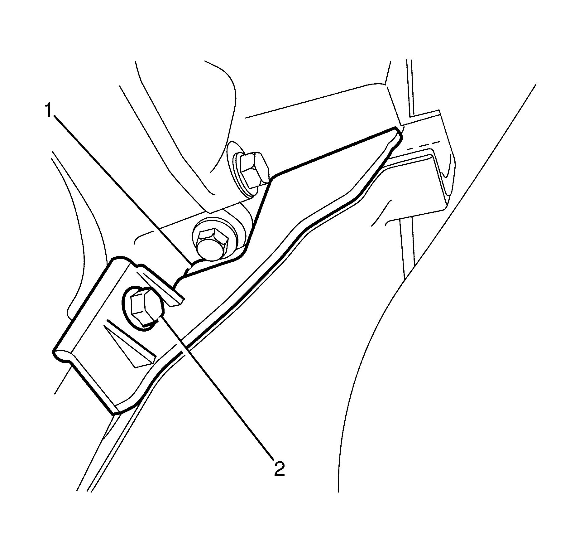
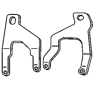
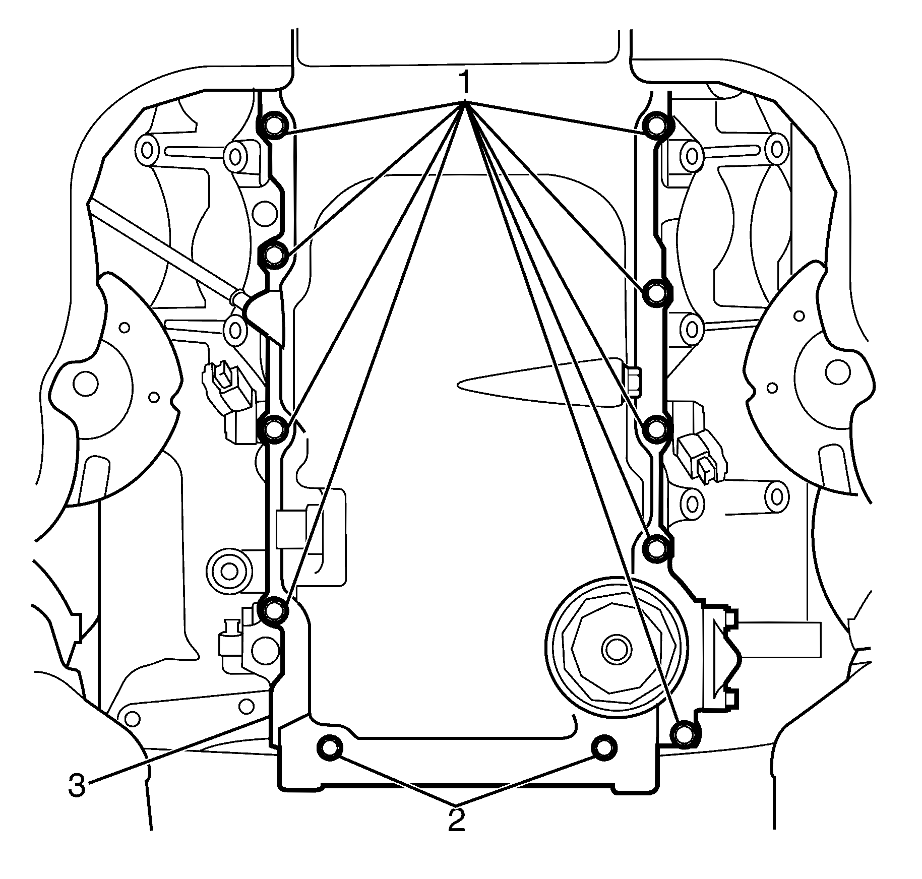
- Remove the left side close out cover to cylinder block retaining bolt (2).
- Remove the left side close out cover (1).
- Remove the right side close out cover to cylinder block retaining bolt (2).
- Remove the right side close out cover (1).
- Mark the intermediate steering shaft (1) in relation to the pinion shaft (3).
- Remove the intermediate steering shaft to pinion shaft retaining bolt (2) and discard.
- Disconnect the intermediate shaft (2) from the pinion shaft (3).
- Remove the steering gear to subframe retaining bolts (1).
- Slide the steering gear forward to gain full access to the sump.
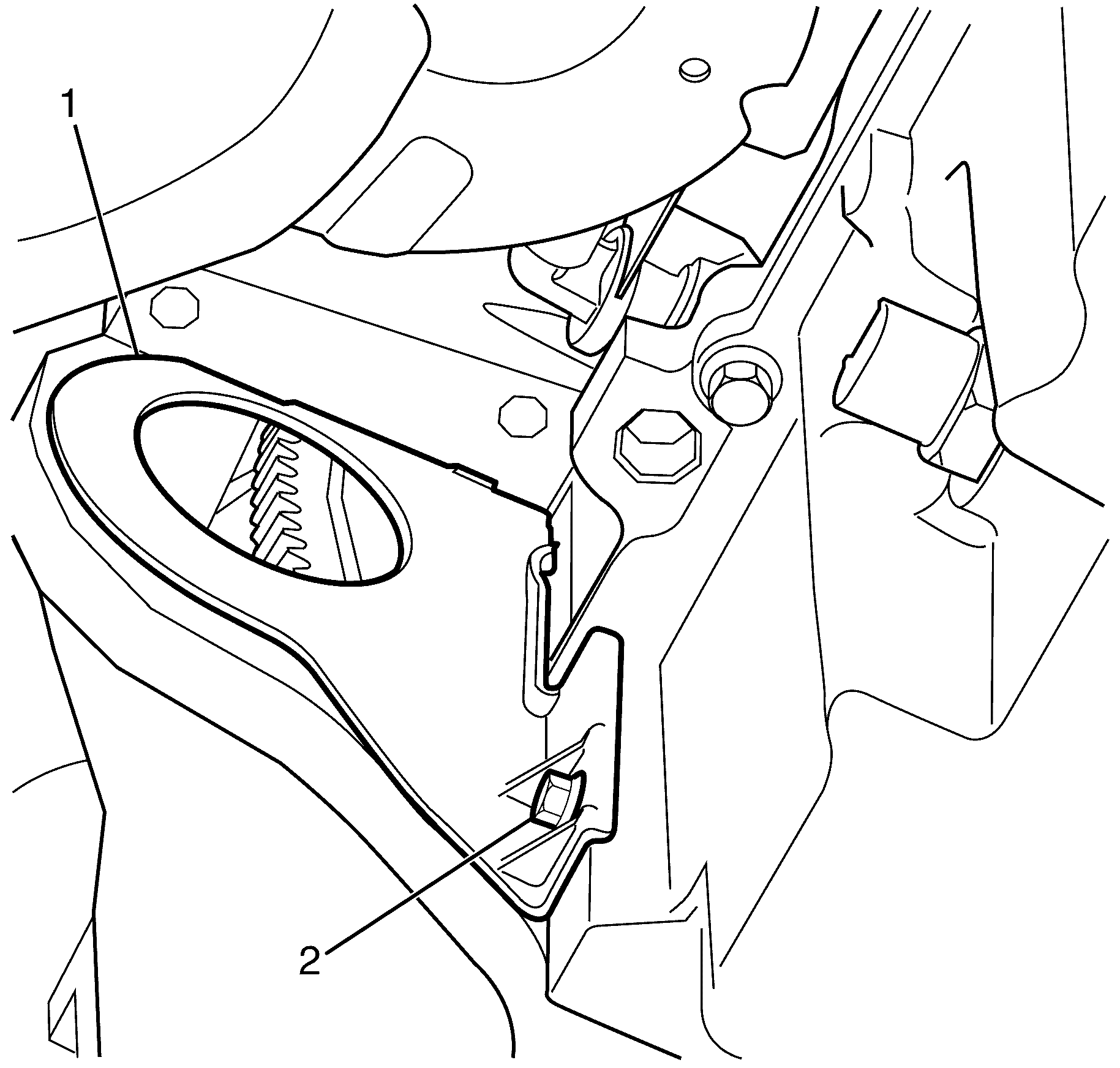
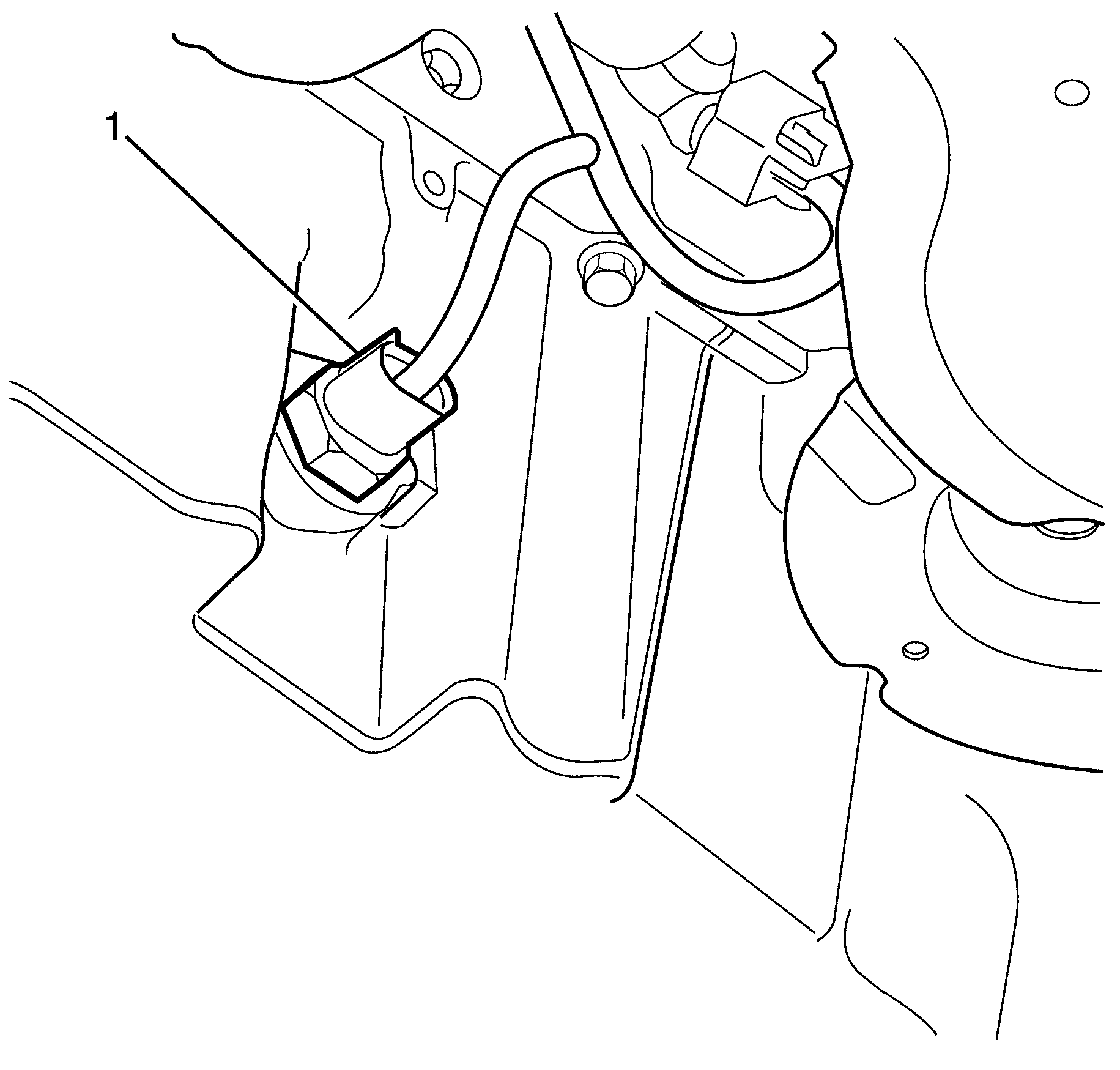
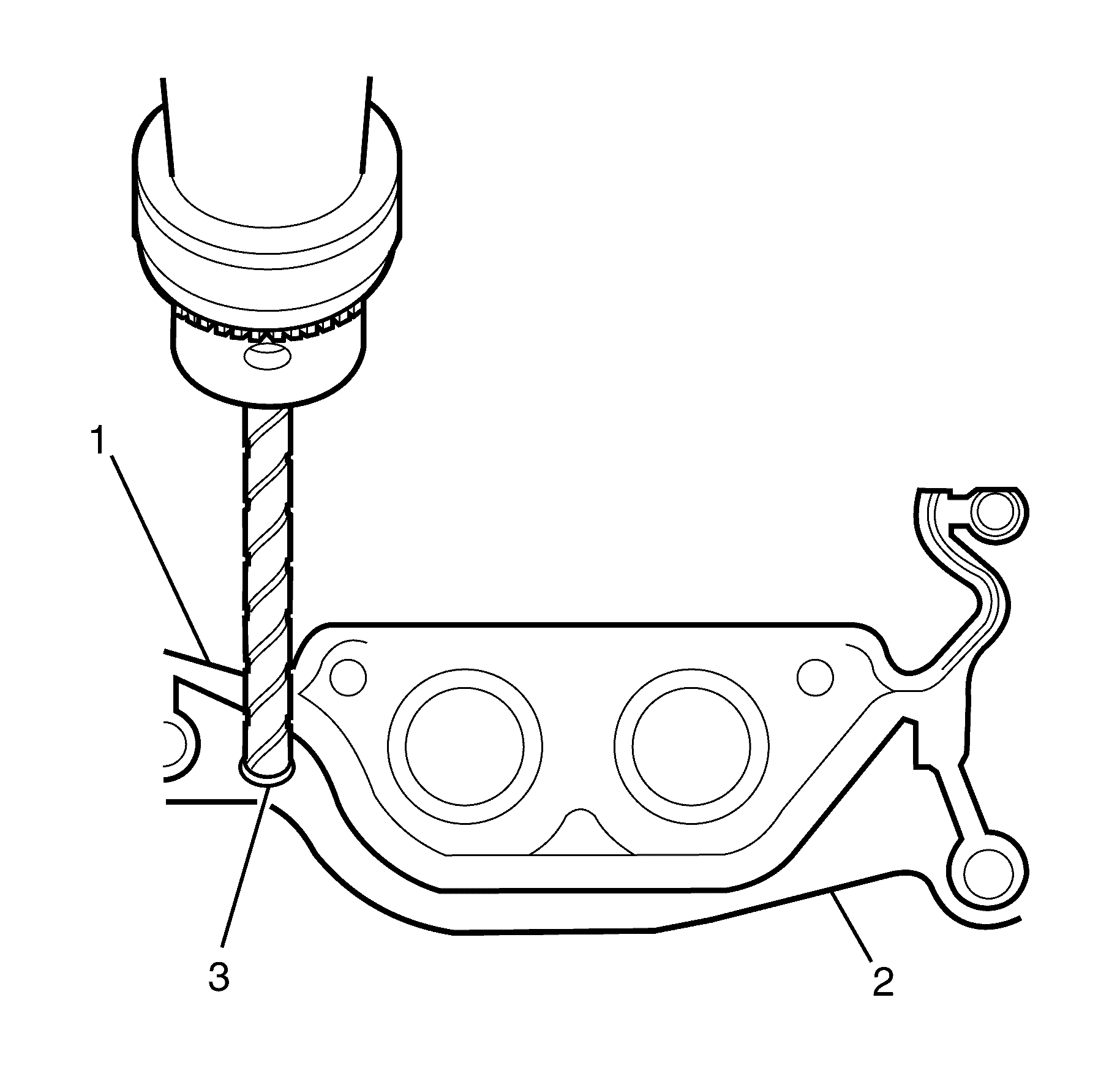
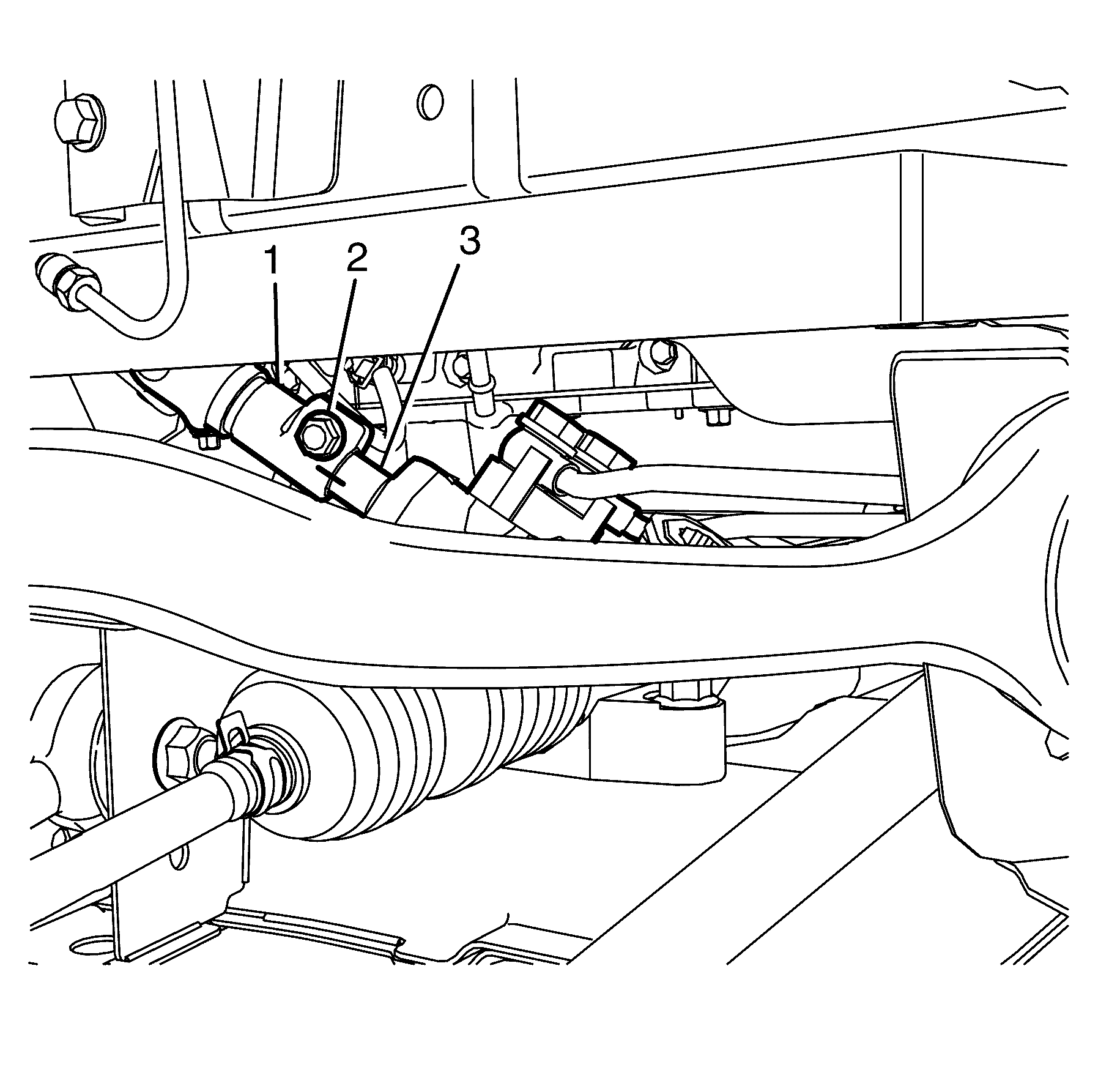
- Disconnect the oil level/temperature sensor electrical connector (1) from the oil level/temperature sensor.
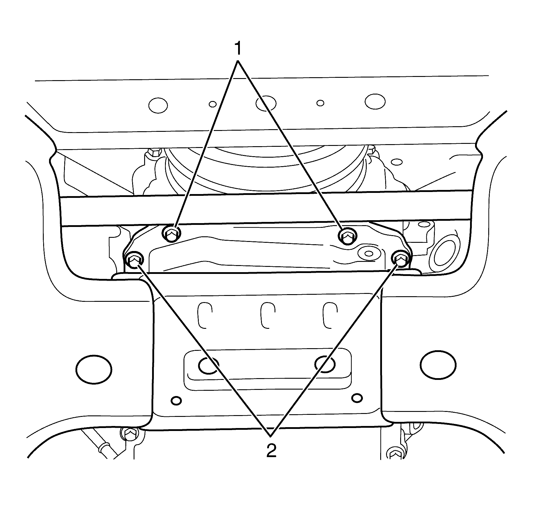
- Remove the transmission to oil pan retaining bolts (1).
- Remove the oil pan to front cover retaining bolts (1).
- Remove the oil pan to cylinder block front retaining bolts (2).
- Lower the vehicle.
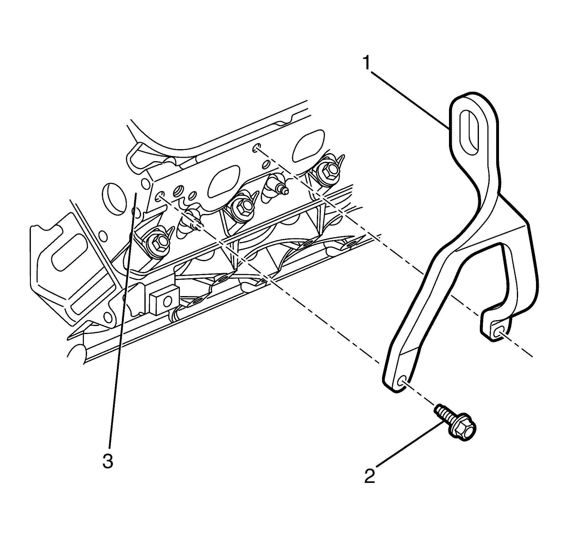
- Position the J 41798 (1) on the cylinder head (3).
- Install the J 41798 to cylinder head retaining bolts (2).
- Install J 41803 J 41803 and J 28467-B and raise the engine assembly 20mm.
- Raise and support the vehicle. Refer to Lifting and Jacking the Vehicle.
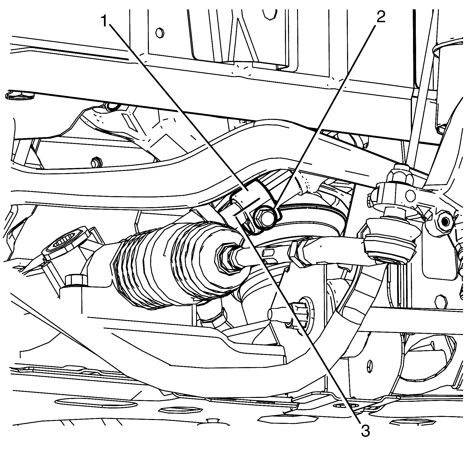
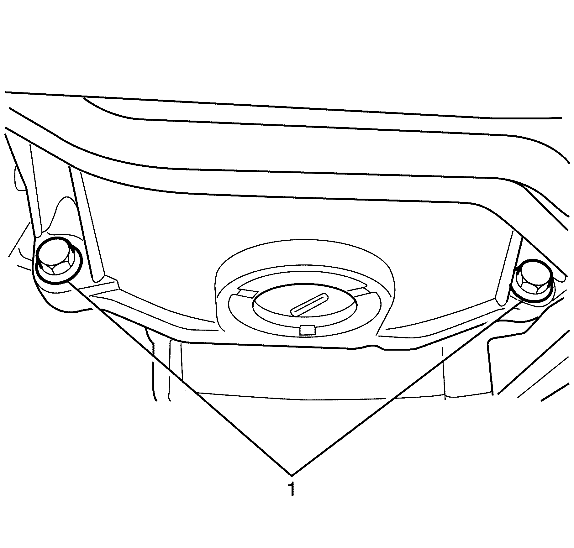
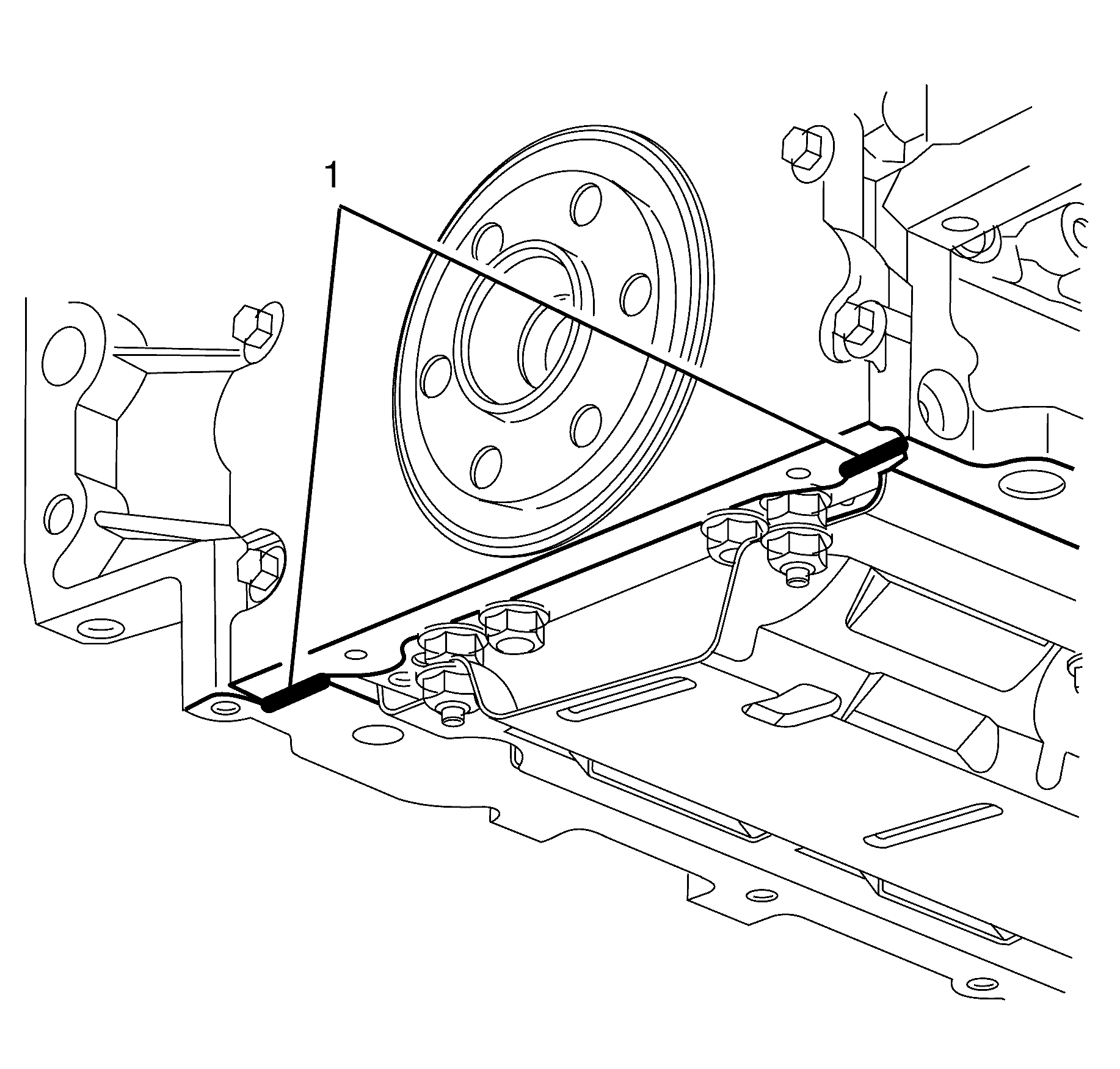
- Remove the lower engine mount to crossmember retaining nut (1) from both engine mounts.
- Remove the oil pan to engine rear cover retaining bolts (2).
- Remove the oil pan to cylinder block retaining bolts (1).
- Remove the oil pan (3).
- Drill out the retaining rivets (3) from the oil pan, if required.
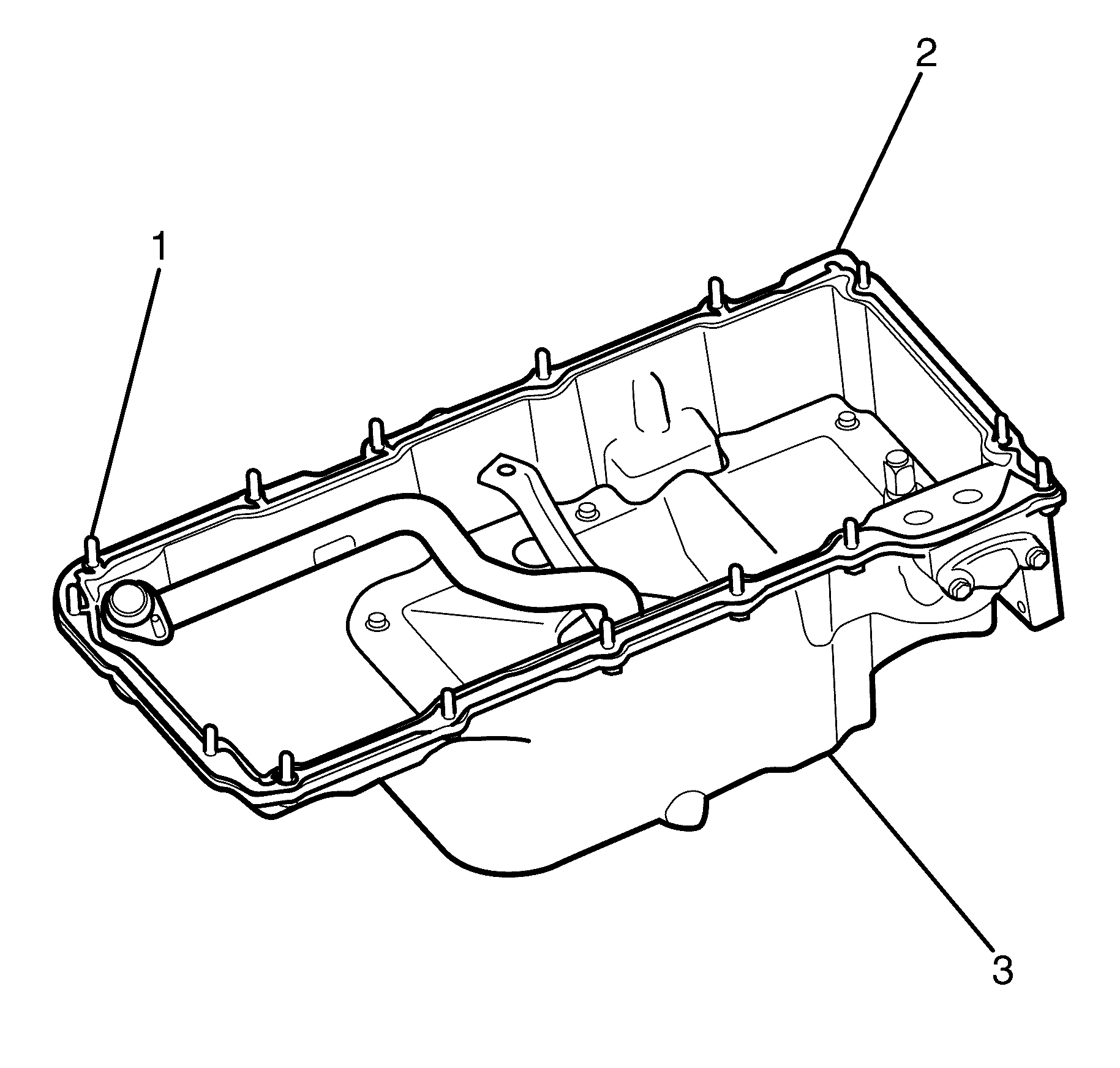
- Remove the oil pan gasket (1) from the oil pan (2).
- Clean and inspect the oil pan as necessary. Refer to Oil Pan Cleaning and Inspection
- Clean the base of the engine block. Refer to Replacing Engine Gaskets
Caution: Refer to Battery Disconnect Caution in the Preface section.
Caution: Refer to Safety Glasses Caution in the Preface section.
Caution: Refer to Vehicle Lifting Caution in the Preface section.
Important: Observing the orientation of the intermediate steering shaft (1) with reference to the pinion shaft (3) will minimise the potential of incorrect steering column assembly alignment.
Important: Secure the steering wheel to prevent rotation otherwise damage to the SIR coil will occur.
Important: Bolts with micro-encapsulated thread sealant must be discarded after removal.
Discard the bolt.
Notice: Refer to Fastener Notice in the Preface section.
Tighten
Tighten the bolts to 50 N·m (36 lb ft).
Important: When lifting the engine assembly, observe the clearance between the rear of the engine assembly and the dash panel.
Important: DO NOT allow foreign material to enter the oil passages of the oil pan, cap, or cover the openings, as required.
Important: Take care not to gouge, score, or damage the oil pan sealing surface.
Important: The oil pan gasket and rivets are single use only components and must be replaced whenever the oil pan is removed from the cylinder block.
Discard the gasket and rivets.
Installation Procedure
- Apply a five mm (0.2 in) bead of sealant 20 mm (0.8 in) long to the engine block (1). Apply the sealant directly onto the tabs of the front cover gasket that protrude into the oil pan surface. Refer to Adhesives, Fluids, Lubricants, and Sealers.
- Apply a five mm (0.2 in) bead of sealant 20 mm (0.8 in) long to the engine block (1). Apply the sealant directly onto the tabs of the rear cover gasket that protrude into the oil pan surface. Refer to Adhesives, Fluids, Lubricants, and Sealers.
- Preassemble the oil pan gasket (2) to the oil pan (3).
- Install the oil pan assembly (3).
- Install the oil pan to cylinder block retaining bolts (1) finger tight. Do not over tighten.
- Install the oil pan to engine rear cover retaining bolts (2) finger tight. Do not over tighten.
- Lower the vehicle.
- Lower the engine to engage the engine mounts to the front subframe.
- Raise the vehicle.
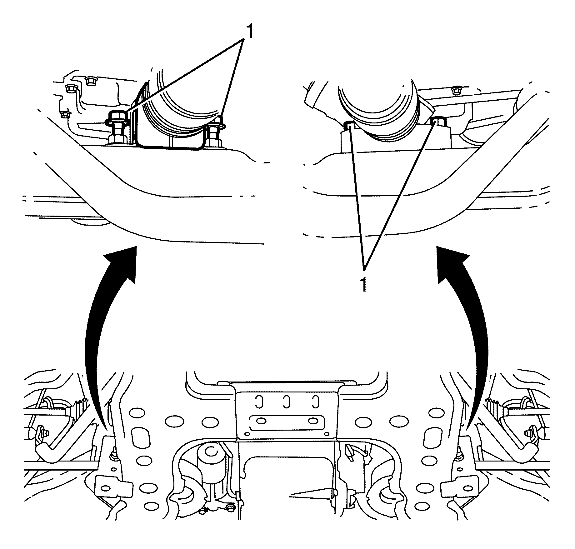
- Install the lower engine mount to front subframe retaining nuts (1) on both engine mounts.
- Lower the vehicle.
- Remove J 41803 and J 28467-B from the engine.
- Remove the J 41798 to cylinder head retaining bolts (2).
- Remove the J 41798 (1) from the cylinder head (3).
- Install the oil pan to front cover retaining bolts (1) finger tight. Do not over tighten.
- Install the oil pan to cylinder block retaining bolts (2) finger tight. Do not over tighten.
- Place a straight edge across the rear of the engine block and the rear of the oil pan at the transmission housing mounting surfaces.
- Align the oil pan until the rear of engine block and the rear of oil pan are flush or even.
- Measure the oil pan-to-engine block alignment.
- Tighten the oil pan to cylinder block retaining bolts (1).
- Tighten the oil pan to engine rear oil seal housing retaining bolts (2).
- Tighten the oil pan to cylinder block retaining bolts (2).
- Tighten the oil pan to front cover retaining bolts (1).
- Position the steering gear in the correct location.
- Install the steering gear to subframe retaining bolts (1).
- Connect the intermediate steering shaft (1) to the pinion shaft (3).
- Install the intermediate steering shaft to pinion shaft NEW retaining bolt (2).
- Install the right side close out cover (1).
- Install the right side close out cover to cylinder block retaining bolt (2).
- Install the left side close out cover (1).
- Install the left side close out cover to cylinder block retaining bolt (2).
- Connect the oil level/temperature sensor electrical connector (1) to the oil level/temperature sensor.
- Install the starter motor. Refer to Starter Motor Replacement.
- Install the air deflector. Refer to Front Air Deflector Replacement.
- Install the engine splash shield. Refer to Engine Splash Shield Replacement.
- Lower the vehicle to the ground
- Connect the battery ground cable. Refer to Battery Negative Cable Disconnection and Connection.
- Replace the engine oil and oil filter. Refer to Engine Oil and Oil Filter Replacement.
Important: The alignment of the structural oil pan is critical. The rear bolt hole locations of the oil pan provide mounting points for the transmission housing. To ensure the rigidity of the powertrain and correct transmission alignment, it is important that the rear of the block and the rear of the oil pan are flush. The rear of the oil pan must NEVER protrude beyond the engine block and transmission housing plane.
Important: The original oil pan gasket is retained and aligned to the oil pan by rivets. When installing a new gasket, it is not necessary to install new oil pan gasket rivets.
It is not necessary to rivet the NEW gasket to the oil pan.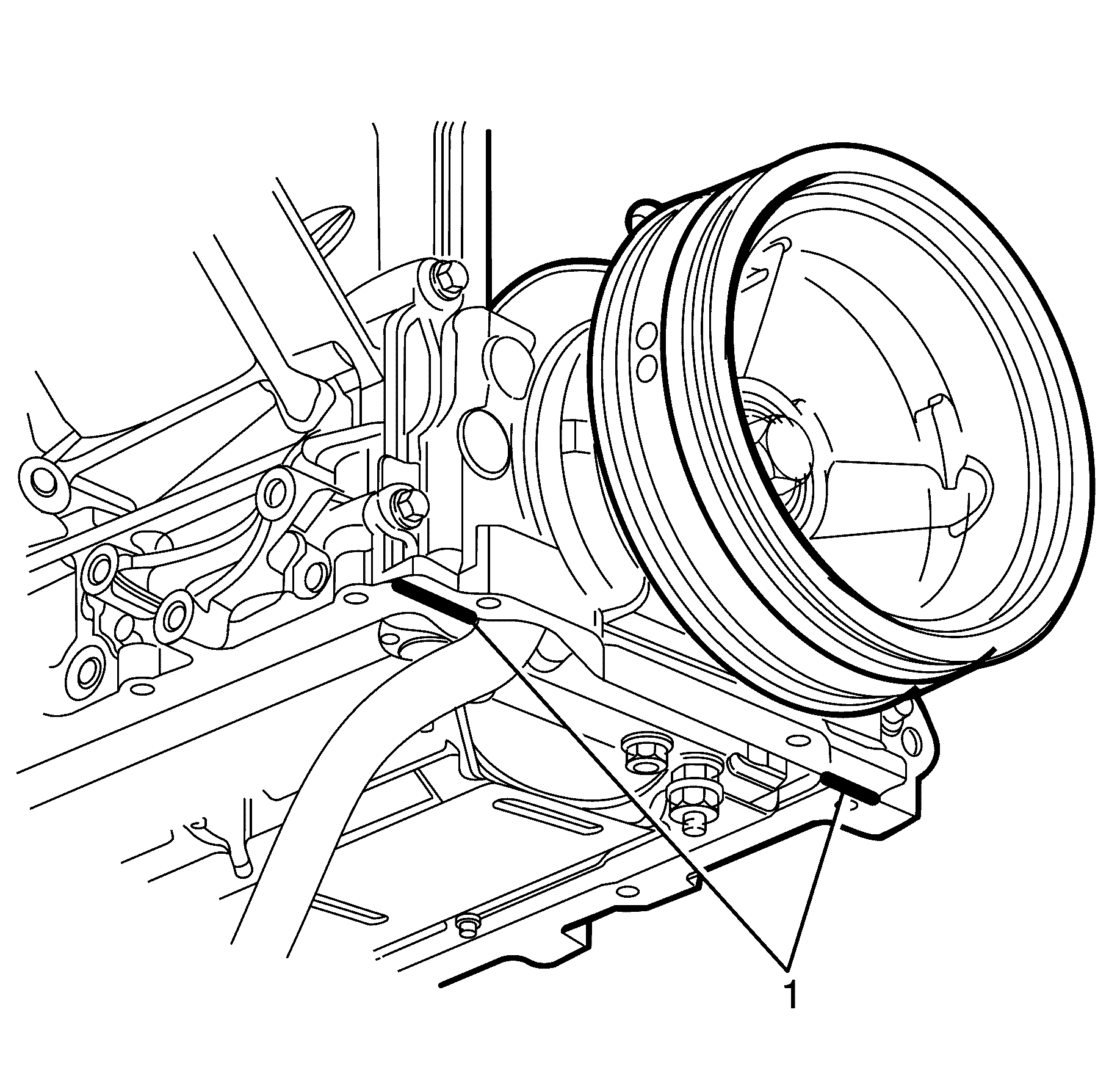
Important: Make sure to align the oil gallery passages in the oil pan and engine block correctly, with the oil pan gasket.
| 3.1. | Install the oil pan gasket (2) to the oil pan (3). |
| 3.2. | Install the oil pan retaining bolts (1) to the oil pan (3) and through the oil pan gasket (2). |
Notice: Refer to Fastener Notice in the Preface section.
Tighten
Tighten the nut to 80 N·m (59 lb ft).
| 19.1. | Place a straight edge across the rear of the engine block and rear of the oil pan at the transmission housing mounting surfaces. |
| Important: The rear of the oil pan must NEVER protrude beyond the engine block and transmission housing mounting surfaces. |
| 19.2. | Insert a feeler gauge between the straight edge and the oil pan transmission housing mounting surface and check to make sure that there is no more than a 0.25 mm (0.01 in) gap between the pan and the straight edge. |
| 19.3. | If the oil pan alignment is not within specifications, remove the oil pan and repeat procedures 17 through to 19. |
Notice: Refer to Fastener Notice in the Preface section.

Tighten
Tighten the bolt to 25 N·m (18 lb ft).
Tighten
Tighten the bolt to 12 N·m (106 lb in).
Tighten
Tighten the bolt to 25 N·m (18 lb ft).
Tighten
Tighten the bolt to 25 N·m (18 lb ft).
Tighten
Tighten the bolts to 65 N·m (48 lb ft).
Important: The intermediate steering shaft and pinion shaft splines must be installed in the position recorded during removal and aligned with the marks previously made.
Tighten
Tighten the bolt to 25 N·m (18 lb ft).
Tighten
Tighten the bolt to 12 N·m (106 lb in).
Tighten
Tighten the bolt to 12 N·m (106 lb in).
Oil Pan Replacement RHD
Removal Procedure
- Disconnect the battery ground cable. Refer to Battery Negative Cable Disconnection and Connection.
- Raise and support the vehicle. Refer to Lifting and Jacking the Vehicle.
- Remove the air deflector. Refer to Front Air Deflector Replacement.
- Drain the engine oil and remove the oil filter. Refer to Engine Oil and Oil Filter Replacement.
- Remove the engine splash shield. Refer to Engine Splash Shield Replacement.
- Remove the starter motor. Refer to Starter Motor Replacement.
- Remove the left side close out cover to cylinder block retaining bolt (2).
- Remove the left side close out cover (1).
- Remove the right side close out cover to cylinder block retaining bolt (2).
- Remove the right side close out cover (1).
- Mark the intermediate steering shaft (1) in relation to the pinion shaft (3).
- Remove the intermediate steering shaft to pinion shaft retaining bolt (2).
- Disconnect the intermediate shaft (2) from the pinion shaft (3).
- Remove the steering gear to subframe retaining bolts (1).
- Slide the steering gear forward to gain full access to the sump.
- Disconnect the oil level/temperature sensor electrical connector (1) from the oil level/temperature sensor.
- Remove the transmission to oil pan retaining bolts (1).
- Remove the oil pan to front cover retaining bolts (1).
- Remove the oil pan to cylinder block front retaining bolts (2).
- Lower the vehicle.
- Position the J 41798 (1) on the cylinder head (3).
- Install the J 41798 to cylinder head retaining bolts (2).
- Install J 41803 and J 28467-B and raise the engine assembly 20mm.
- Raise and support the vehicle. Refer to Lifting and Jacking the Vehicle.
- Remove the lower engine mount to crossmember retaining nut (1) from both engine mounts.
- Lower the vehicle.
- Remove the oil pan to engine rear cover retaining bolts (2).
- Remove the oil pan to cylinder block retaining bolts (1).
- Remove the oil pan (3).
- Drill out the retaining rivets (3) from the oil pan, if required.
- Remove the oil pan gasket (1) from the oil pan (2).
- Clean and inspect the oil pan as necessary. Refer to Oil Pan Cleaning and Inspection
- Clean the base of the engine block. Refer to Replacing Engine Gaskets
Caution: Refer to Battery Disconnect Caution in the Preface section.
Caution: Refer to Safety Glasses Caution in the Preface section.
Caution: Refer to Vehicle Lifting Caution in the Preface section.
Important: Observing the orientation of the intermediate steering shaft (1) with reference to the pinion shaft (3) will minimise the potential of incorrect steering column assembly alignment.
Important: Bolts with micro-encapsulated thread sealant must be discarded after removal.
Important: Make sure the bolt hole is thoroughly cleaned and all micro-encapsulated thread sealant is removed.
Discard the bolt.
Notice: Refer to Fastener Notice in the Preface section.
Tighten
Tighten the bolts to 50 N·m (36 lb ft).
Important: When lifting the engine assembly, observe the clearance between the rear of the engine assembly and the dash panel.
Important: DO NOT allow foreign material to enter the oil passages of the oil pan, cap, or cover the openings, as required.
Important: Take care not to gouge, score, or damage the oil pan sealing surface.
Important: The oil pan gasket and rivets are single use only components and must be replaced whenever the oil pan is removed from the cylinder block.
Discard the gasket and rivets.
Installation Procedure
- Apply a five mm (0.2 in) bead of sealant 20 mm (0.8 in) long to the engine block (1). Apply the sealant directly onto the tabs of the front cover gasket that protrude into the oil pan surface. Refer to Adhesives, Fluids, Lubricants, and Sealers.
- Apply a five mm (0.2 in) bead of sealant 20 mm (0.8 in) long to the engine block (1). Apply the sealant directly onto the tabs of the rear cover gasket that protrude into the oil pan surface. Refer to Adhesives, Fluids, Lubricants, and Sealers.
- Preassemble the oil pan gasket (2) to the oil pan (3).
- Install the oil pan assembly (3).
- Install the oil pan to cylinder block retaining bolts (1) finger tight. Do not over tighten.
- Install the oil pan to engine rear cover retaining bolts (2) finger tight. Do not over tighten.
- Lower the vehicle.
- Lower the engine to engage the engine mounts to the front subframe.
- Raise the vehicle.
- Install the lower engine mount to front subframe retaining nuts (1) on both engine mounts.
- Lower the vehicle.
- Remove J 41803 and J 28467-B from the engine.
- Remove the J 41798 (1) from the cylinder head (2).
- Install the oil pan to front cover retaining bolts (1) finger tight. Do not over tighten.
- Install the oil pan to cylinder block retaining bolts (2) finger tight. Do not over tighten.
- Place a straight edge across the rear of the engine block and the rear of the oil pan at the transmission housing mounting surfaces.
- Align the oil pan until the rear of engine block and the rear of oil pan are flush or even.
- Measure the oil pan-to-engine block alignment.
- Tighten the M8 oil pan to cylinder block retaining bolts (1).
- Tighten the M6 oil pan to engine rear oil seal housing retaining bolts (2).
- Tighten the oil pan to cylinder block retaining bolts (2).
- Tighten the oil pan to front cover retaining bolts (1).
- Position the steering gear in the correct location.
- Install the steering gear to subframe retaining bolts (1).
- Connect the intermediate steering shaft (1) to the pinion shaft (3).
- Install the intermediate steering shaft to pinion shaft NEW retaining bolt (2).
- Install the right side close out cover (1).
- Install the right side close out cover to cylinder block retaining bolt (2).
- Install the left side close out cover (1).
- Install the left side close out cover to cylinder block retaining bolt (2).
- Connect the oil level/temperature sensor electrical connector (1) to the oil level/temperature sensor.
- Install the starter motor. Refer to Starter Motor Replacement.
- Install the air deflector. Refer to Front Air Deflector Replacement.
- Install the engine splash shield. Refer to Engine Splash Shield Replacement.
- Lower the vehicle to the ground
- Connect the battery ground cable. Refer to Battery Negative Cable Disconnection and Connection.
- Replace the engine oil and oil filter. Refer to Engine Oil and Oil Filter Replacement.
Important: The alignment of the structural oil pan is critical. The rear bolt hole locations of the oil pan provide mounting points for the transmission housing. To ensure the rigidity of the powertrain and correct transmission alignment, it is important that the rear of the block and the rear of the oil pan are flush. The rear of the oil pan must NEVER protrude beyond the engine block and transmission housing plane.
Important: The original oil pan gasket is retained and aligned to the oil pan by rivets. When installing a new gasket, it is not necessary to install new oil pan gasket rivets.
It is not necessary to rivet the NEW gasket to the oil pan.
Important: Make sure to align the oil gallery passages in the oil pan and engine block correctly, with the oil pan gasket.
| 3.1. | Install the oil pan gasket (2) to the oil pan (3). |
| 3.2. | Install the oil pan retaining bolts (1) to the oil pan (3) and through the oil pan gasket (2). |
Notice: Refer to Fastener Notice in the Preface section.
Tighten
Tighten the nut to 80 N·m (59 lb ft).
| 18.1. | Place a straight edge across the rear of the engine block and rear of the oil pan at the transmission housing mounting surfaces. |
| Important: The rear of the oil pan must NEVER protrude beyond the engine block and transmission housing mounting surfaces. |
| 18.2. | Insert a feeler gauge between the straight edge and the oil pan transmission housing mounting surface and check to make sure that there is no more than a 0.25 mm (0.01 in) gap between the pan and the straight edge. |
| 18.3. | If the oil pan alignment is not within specifications, remove the oil pan and repeat procedures 17 through to 19. |
Notice: Refer to Fastener Notice in the Preface section.
Tighten
Tighten the bolt to 25 N·m (18 lb ft).
Tighten
Tighten the bolt to 12 N·m (106 lb in).
Tighten
Tighten the bolt to 25 N·m (18 lb ft).
Tighten
Tighten the bolt to 25 N·m (18 lb ft).
Tighten
Tighten the bolts to 65 N·m (48 lb ft).
Important: The intermediate steering shaft and pinion shaft splines must be installed in the position recorded during removal and aligned with the marks previously made.
Tighten
Tighten the bolt to 25 N·m (18 lb ft).
Tighten
Tighten the bolt to 12 N·m (106 lb in).
Tighten
Tighten the bolt to 12 N·m (106 lb in).
