Tools Required
| • | J 45059 Angle Meter |
| • | J 42385-100 Head/Main Bolt Thread Repair Kit |
Removal Procedure
- Remove the air inlet grille panel. Refer to Air Inlet Grille Panel Replacement.
- Remove the engine cover. Refer to Engine Cover Replacement.
- Depressurize the fuel system. Refer to Fuel Pressure Relief.
- Disconnect the battery ground cable. Refer to Battery Negative Cable Disconnection and Connection.
- Drain the cooling system. Refer to Cooling System Draining and Filling.
- Remove the intake manifold assembly. Refer to Intake Manifold Replacement.
- Remove the engine coolant air bleed pipe and cover. Refer to Engine Coolant Air Bleed Hose Replacement.
- Remove the right side ignition coils. Refer to Ignition Coil Replacement.
- Remove the spark plugs. Refer to Spark Plug Replacement.
- Remove the oil level indicator and tube. Refer to Oil Level Indicator and Tube Replacement.
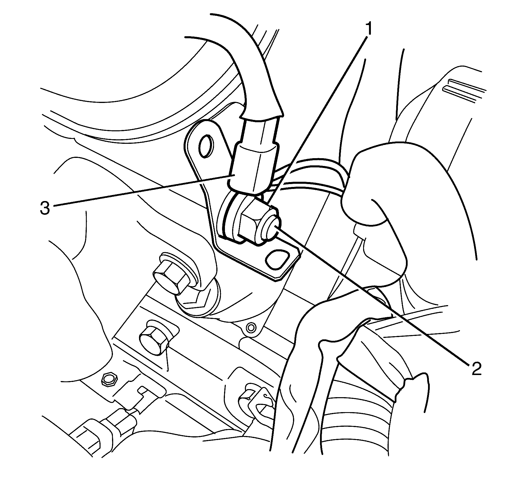
- Remove the vehicle body ground cable to cylinder head retaining nut (1).
- Remove the vehicle body ground cable (3) from the cylinder head stud (2).
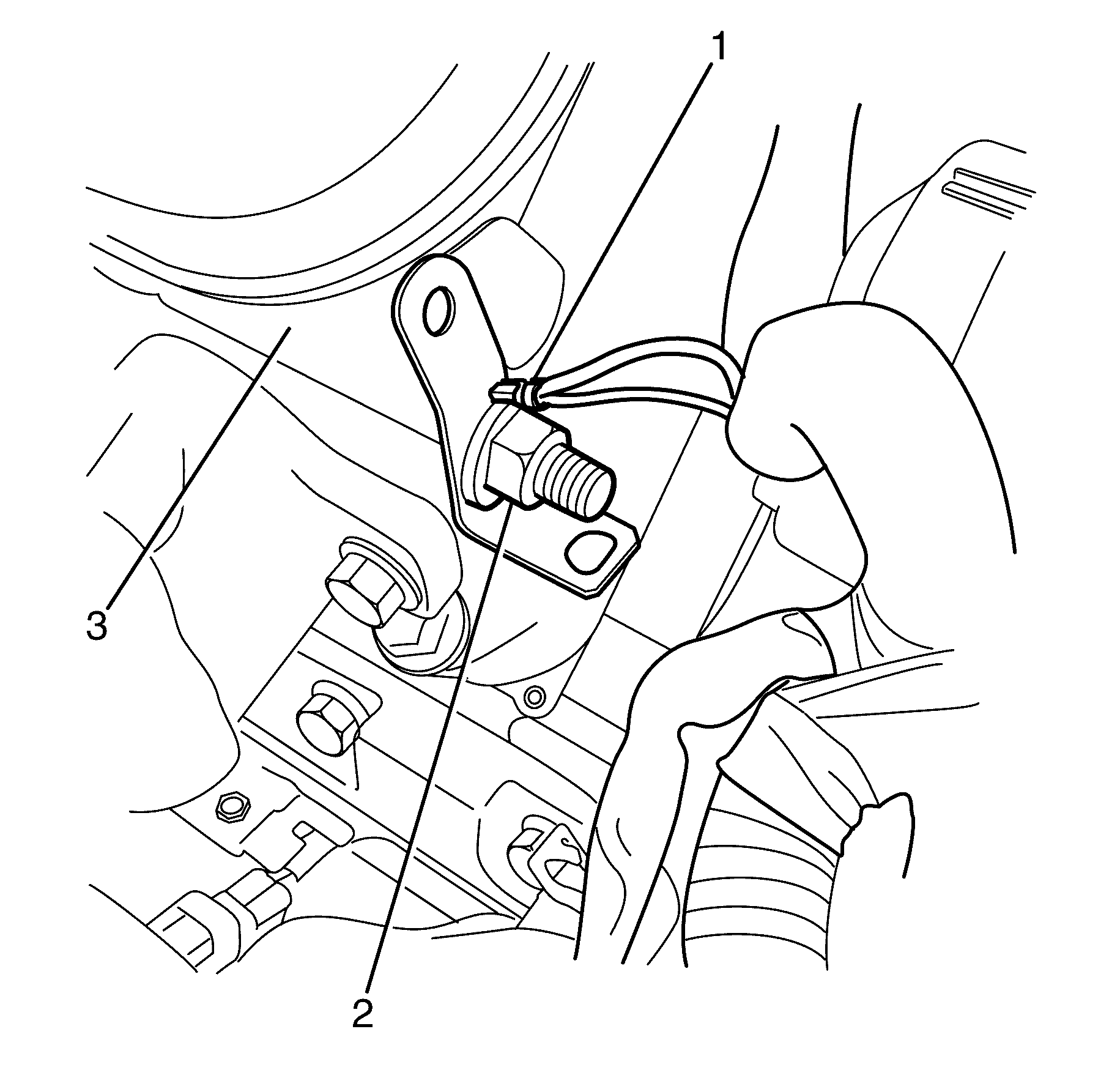
- Remove the cylinder head stud (3) from the cylinder head (2) and secure the wiring harness ground (1) away from the cylinder head (2).
- Remove the right side exhaust manifold. Refer to Exhaust Manifold Replacement - Right Side.
- Remove the right side valve rocker arm cover. Refer to Valve Rocker Arm Cover Replacement - Right Side.
- Remove the right side valve rocker arms and pushrods. Refer to Valve Rocker Arm and Push Rod Replacement.
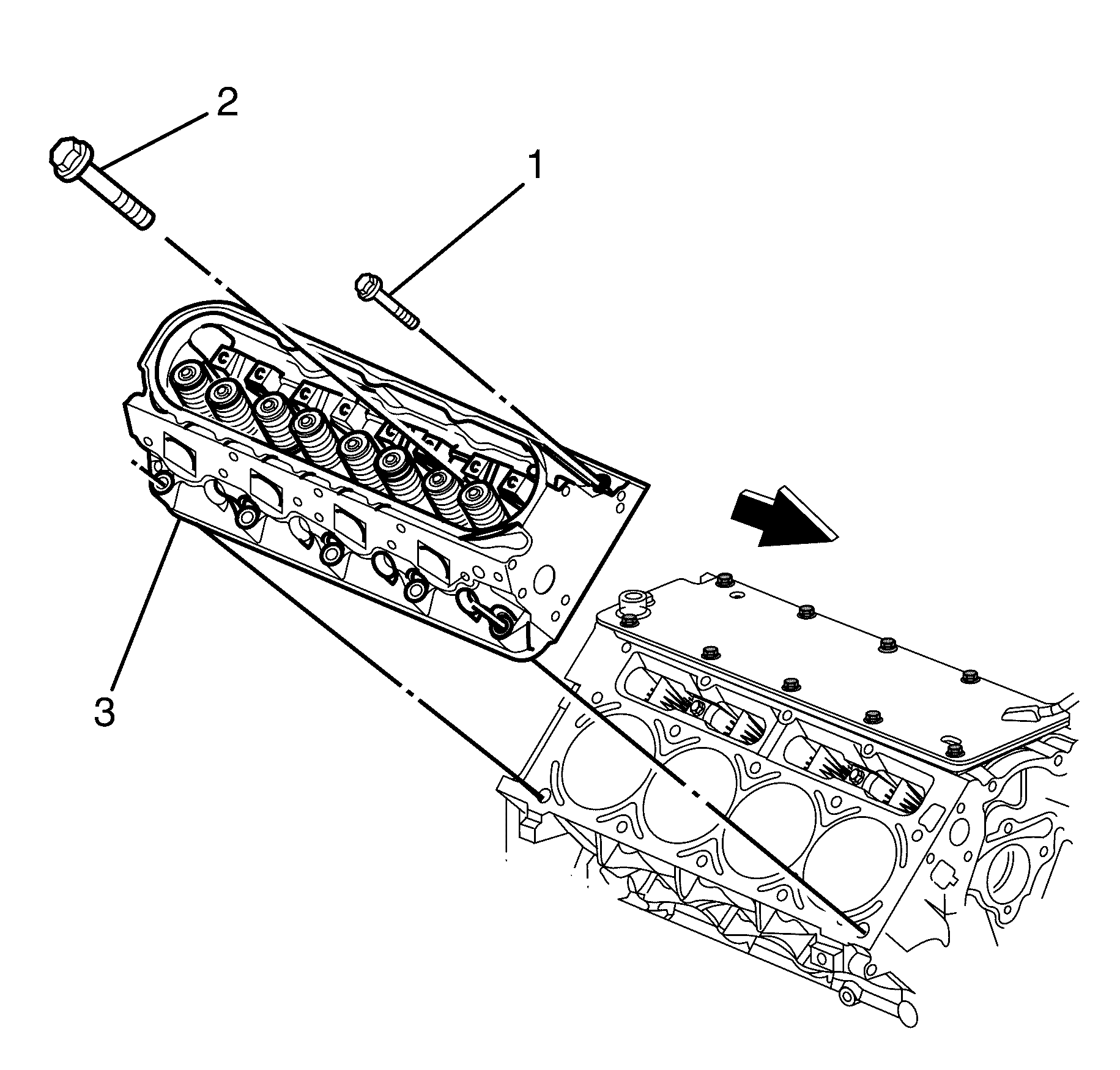
- Remove and discard the cylinder head bolts (1) 10 places, (2) 5 places.
- Remove the cylinder head (3).
- Remove the cylinder head gasket (1).
- Clean and inspect the cylinder head and the cylinder block sealing surfaces. Refer to Cylinder Head Cleaning and Inspection and Engine Block Cleaning and Inspection.
- If necessary, perform the following steps:
Caution: Refer to Battery Disconnect Caution in the Preface section.
Important: The cylinder head bolts are torque to yield bolts and are single use only fasteners.
Discard the bolts.
Notice: After removal, place the cylinder head on 2 wood blocks in order to prevent damage to the sealing surfaces.
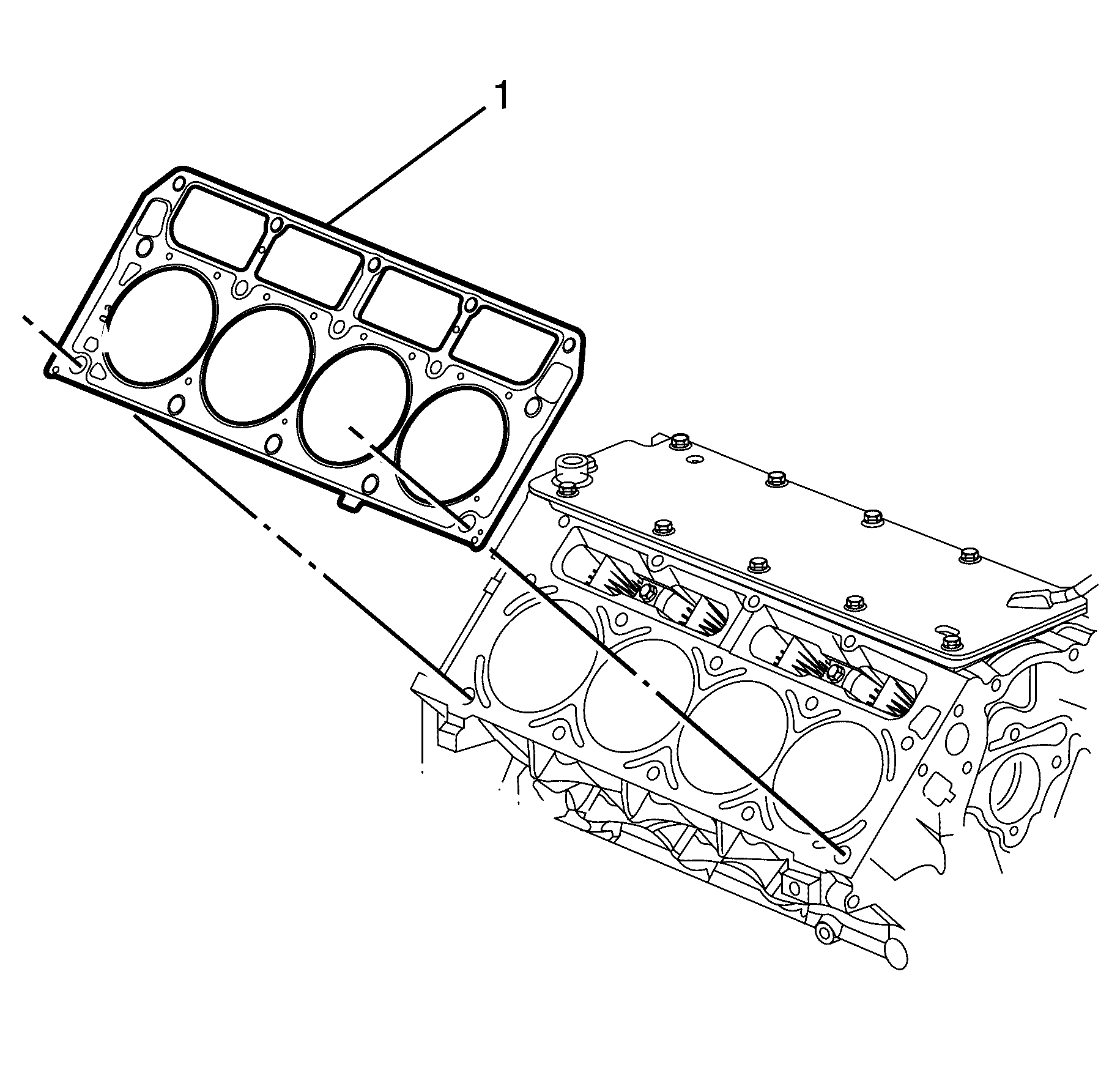
Important: Cylinder head gaskets must be discarded whenever the cylinder head has been removed from the cylinder block.
Discard the gasket.
Disassemble the cylinder head. Refer to Cylinder Head Disassemble.
Installation Procedure
- If necessary, perform the following steps:
- Install the locating sleeves (2) into the cylinder block (1).
- Install the NEW cylinder head gasket (3) correctly over the locating sleeves.
- Install the cylinder head with the exhaust manifold to the engine. Refer to Cylinder Head Installation - Right Side.
- Install the right side valve rocker arms and pushrods. Refer to Valve Rocker Arm and Push Rod Replacement.
- Install the right side valve rocker arm cover. Refer to Valve Rocker Arm Cover Replacement - Right Side.
- Remove the right side exhaust manifold. Refer to Exhaust Manifold Replacement - Right Side.
- Position the wiring harness ground (1) on the cylinder head (2).
- Install the cylinder head stud (3) to the cylinder head (2).
- Position the vehicle body ground cable (3) on the cylinder head stud (2).
- Install the vehicle body ground cable to cylinder head retaining nut (1).
- Install the oil level indicator and tube. Refer to Oil Level Indicator and Tube Replacement.
- Install the spark plugs. Refer to Spark Plug Replacement.
- Install the right side ignition coils. Refer to Ignition Coil Replacement.
- Install the engine coolant air bleed pipe and cover. Refer to Engine Coolant Air Bleed Hose Replacement.
- Install the intake manifold assembly. Refer to Intake Manifold Replacement.
- Refill the cooling system. Refer to Cooling System Draining and Filling.
- Connect the battery ground cable. Refer to Battery Negative Cable Disconnection and Connection.
- Install the engine cover. Refer to Engine Cover Replacement.
- Install the air inlet grille panel. Refer to Air Inlet Grille Panel Replacement.
Assemble the cylinder head. Refer to Cylinder Head Assemble.
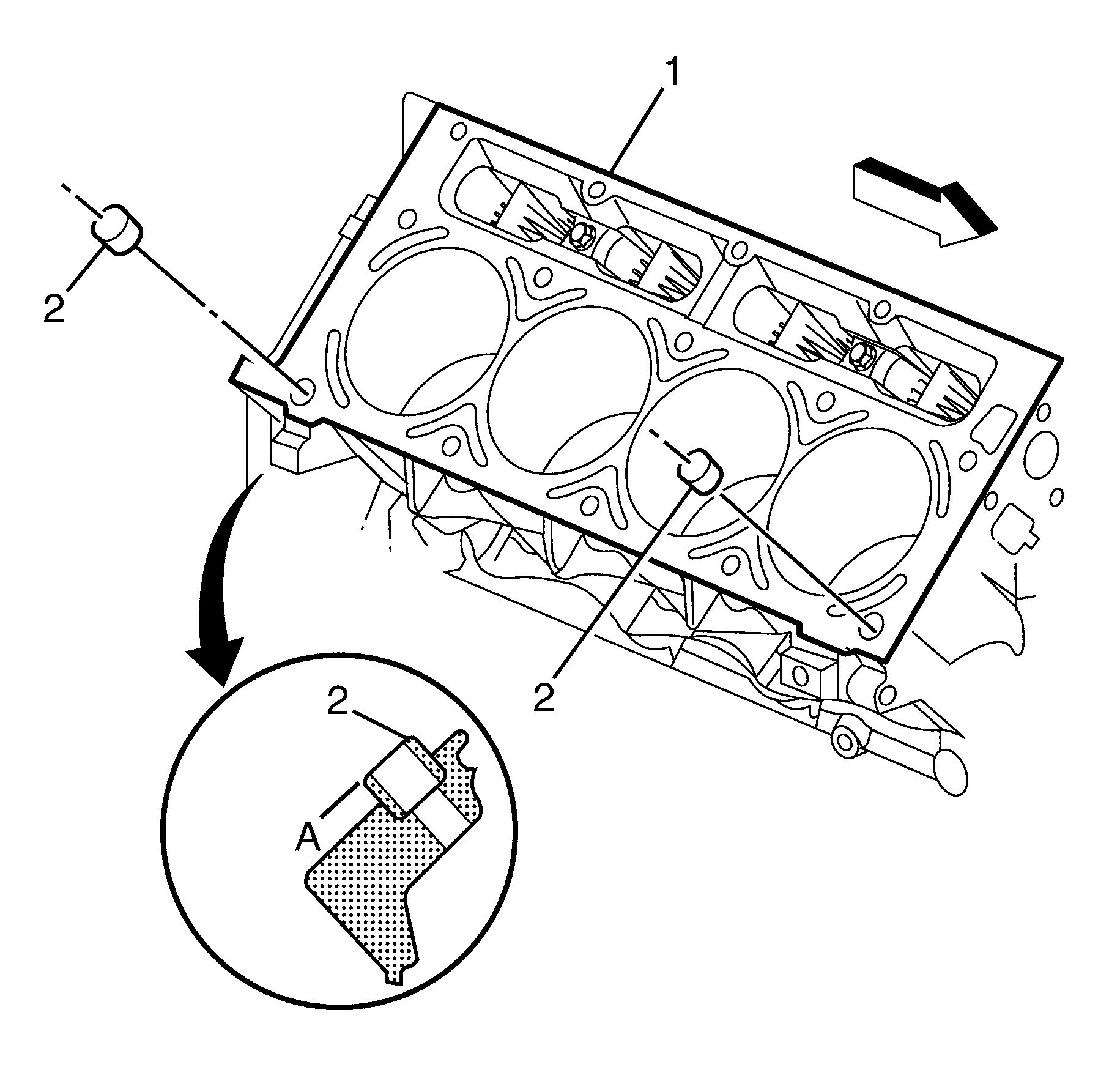
Important: Make sure the locating sleeves (2) are correctly installed to the maximum height (A) of 8.3 mm (0.33 in).
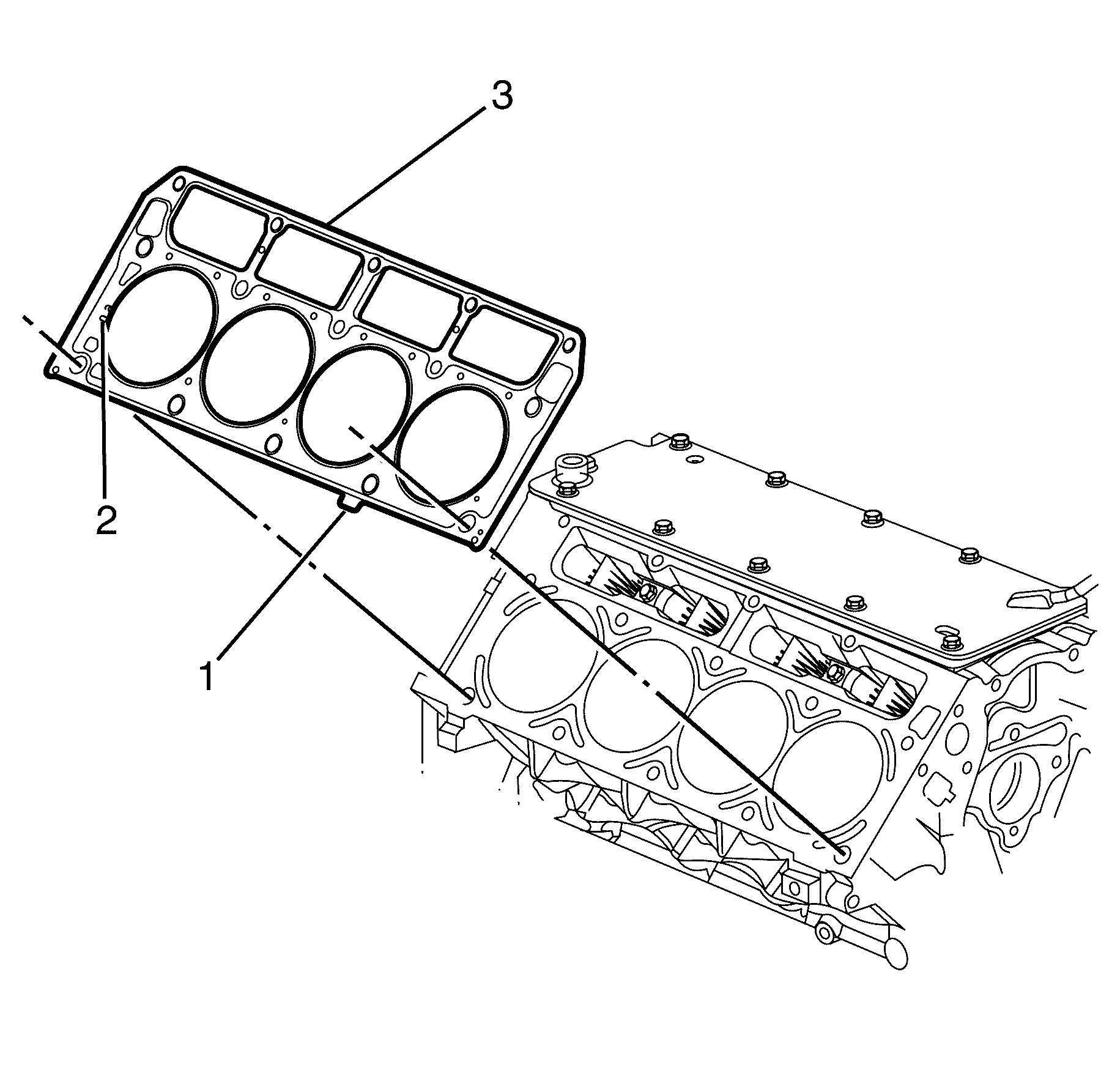
Important: The cylinder head gasket (3) will fit on either side of the engine. Make sure the tab on the cylinder head gasket (1) is located towards the front half point and the stamping FRONT on the cylinder head gasket (2) is facing the front of the engine.
Important: Do not use any type of sealant on the cylinder head gasket (1), unless specified.

Notice: Refer to Fastener Notice in the Preface section.
Tighten
Tighten the stud to 30 N·m(22 lb ft).

Tighten
Tighten the nut to 12 N·m(106 lb ft).
