Parking Brake Release Handle Assembly Replacement LHD
Removal Procedure
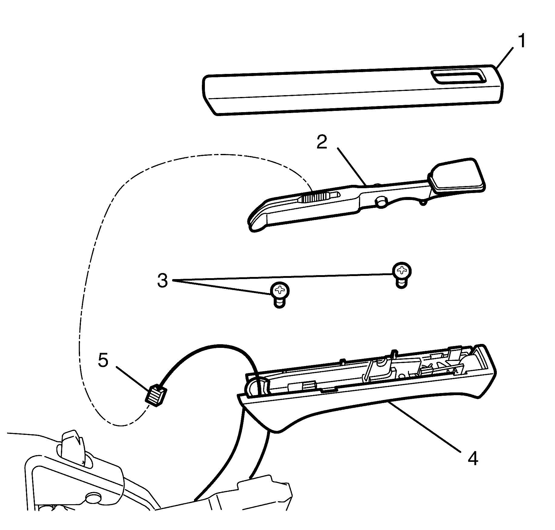
- Remove the front floor console assembly. Refer to Front Floor Console Replacement .
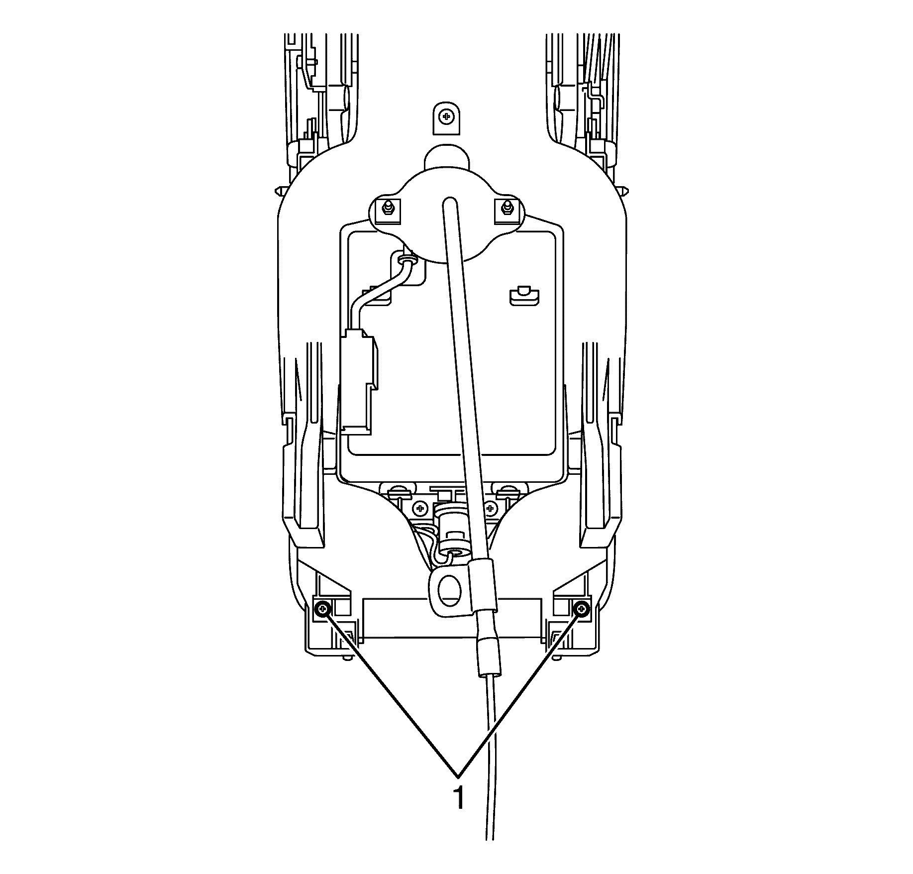
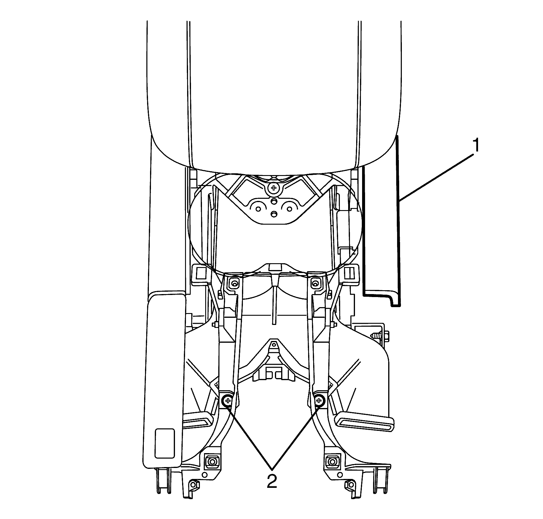
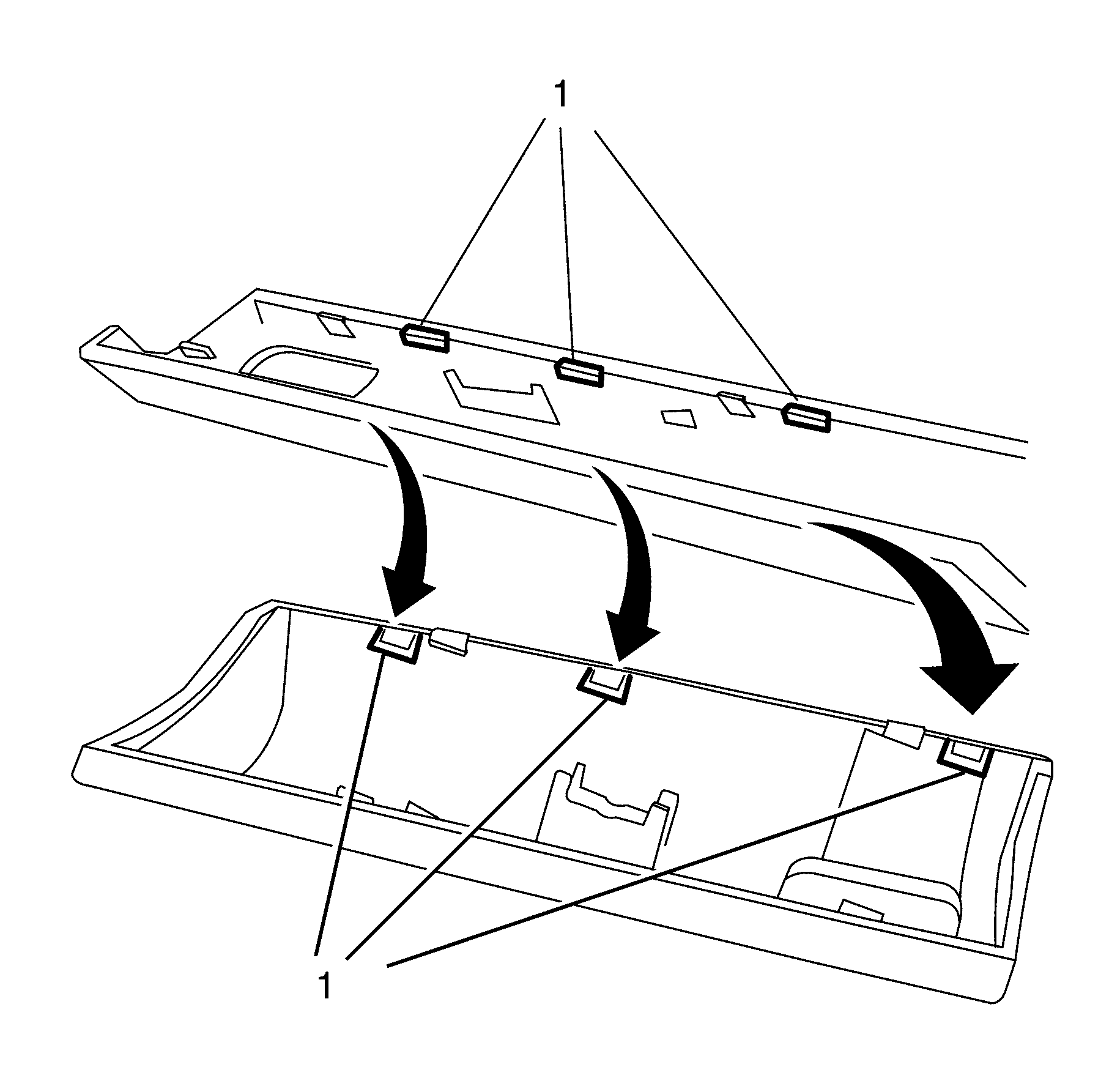
- Remove the rear front floor console cover assembly to rear floor air outlet duct retaining screws (1).
- Remove the front floor console cover assembly to rear floor air outlet duct retaining screws (2).
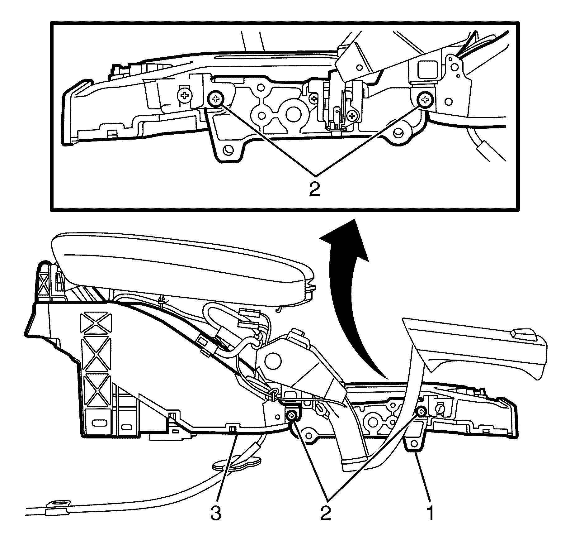
- Remove the front floor console cover assembly (1).
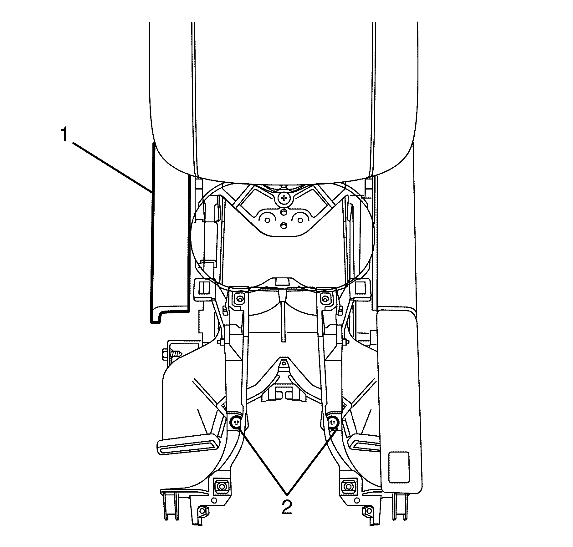
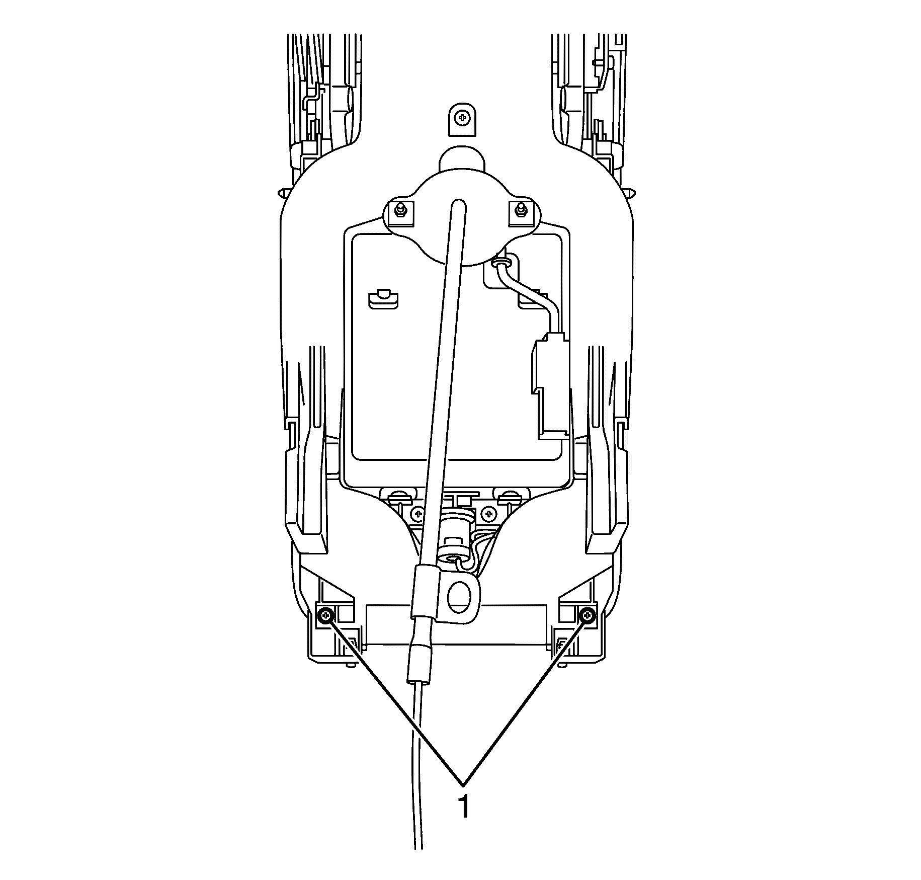
- Remove the rear floor air outlet duct to park brake assembly retaining screw (1).
- Remove the rear floor air outlet duct to park brake assembly retaining screws (2).
- Remove the park brake assembly (3) from the rear floor air outlet duct (1).
Disassembly Procedure
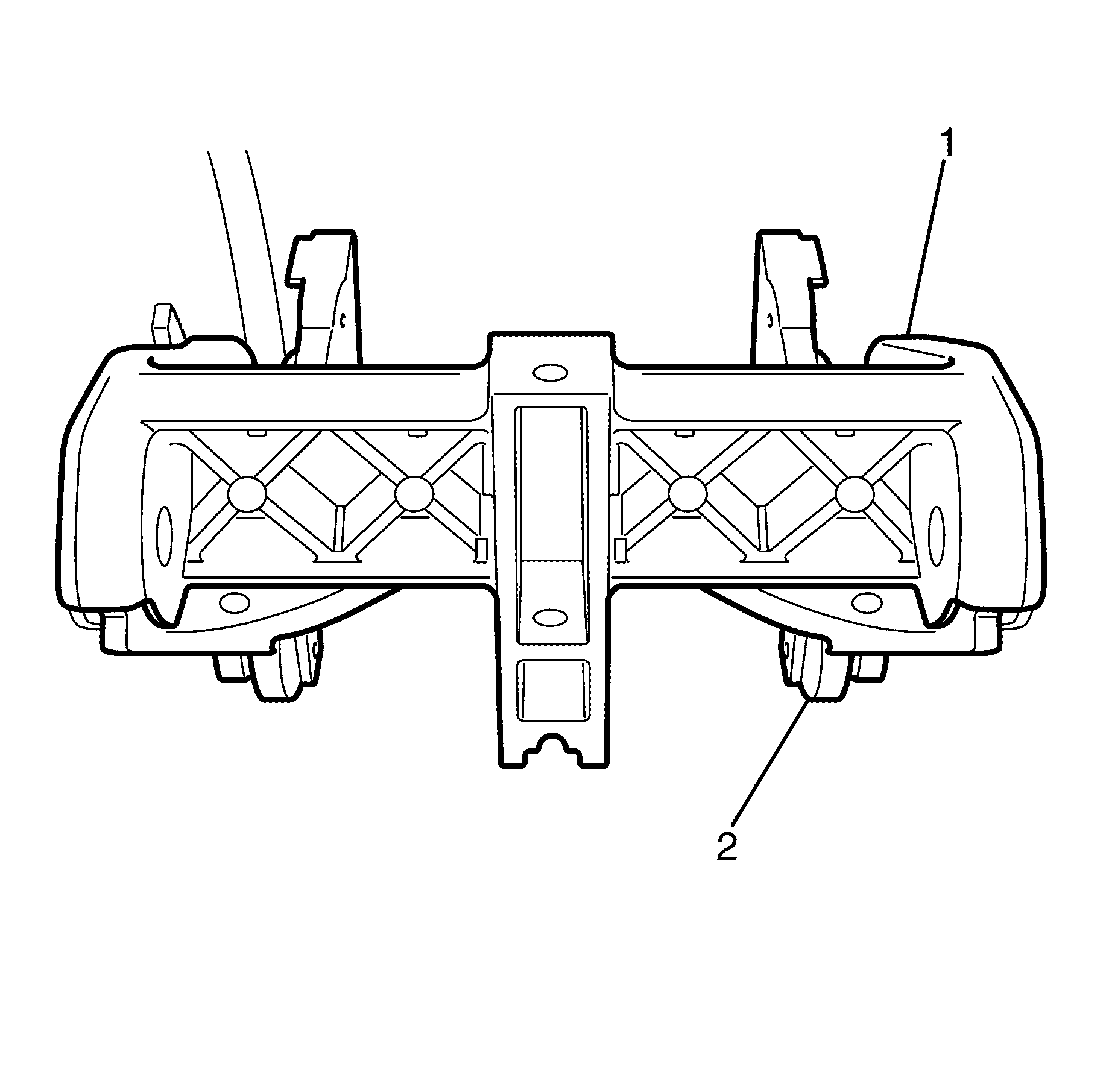
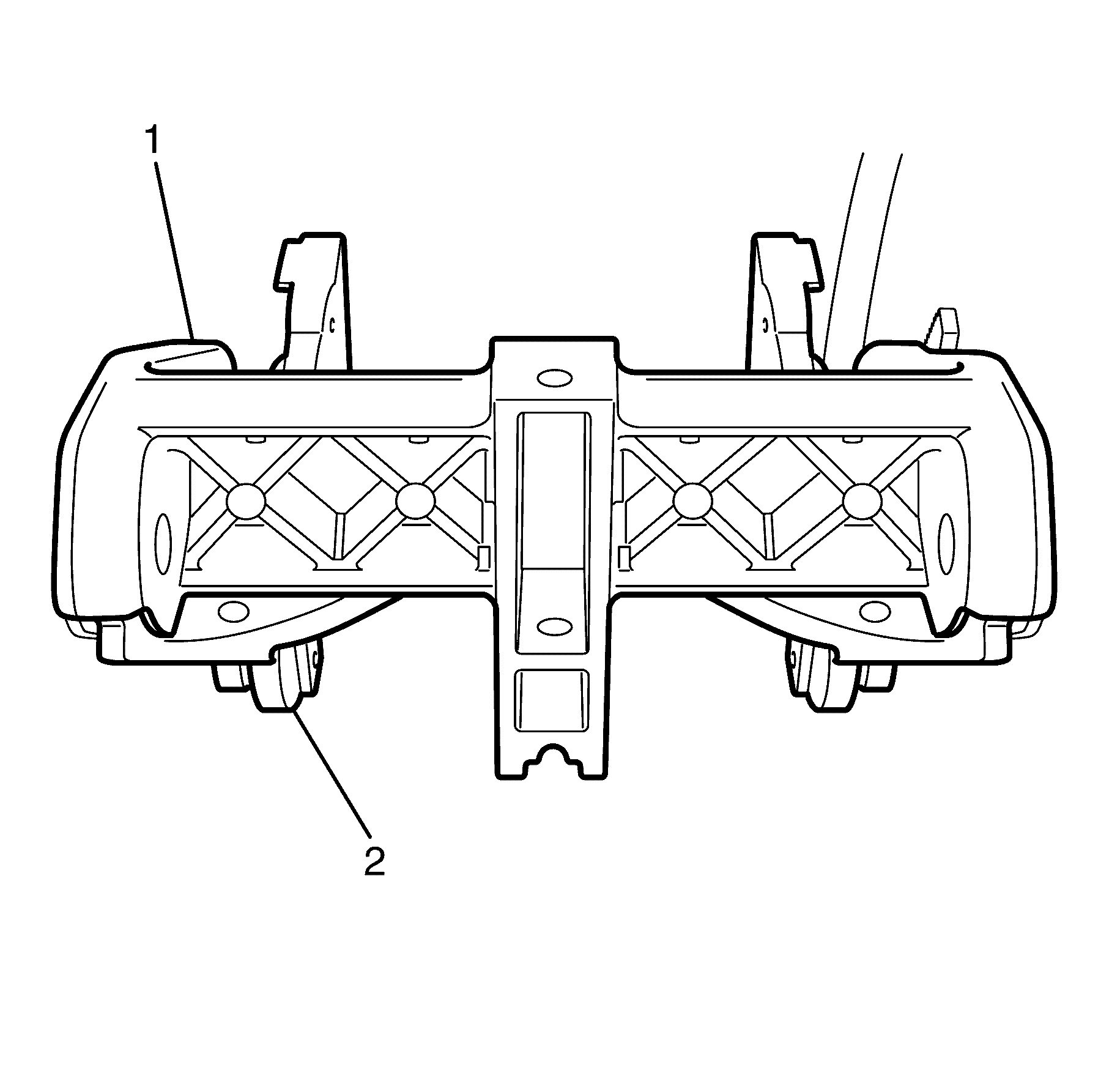
- Remove the park brake lever upper grip (1) and discard.
- Detach the park brake lever cable (5) from the park brake lever button (2).
- Remove the park brake lever button (2) and the park brake lever spring.
- Remove the park brake lever to park brake lever lower grip retaining screws (3).
- Remove the park brake lever lower grip (4) and discard.
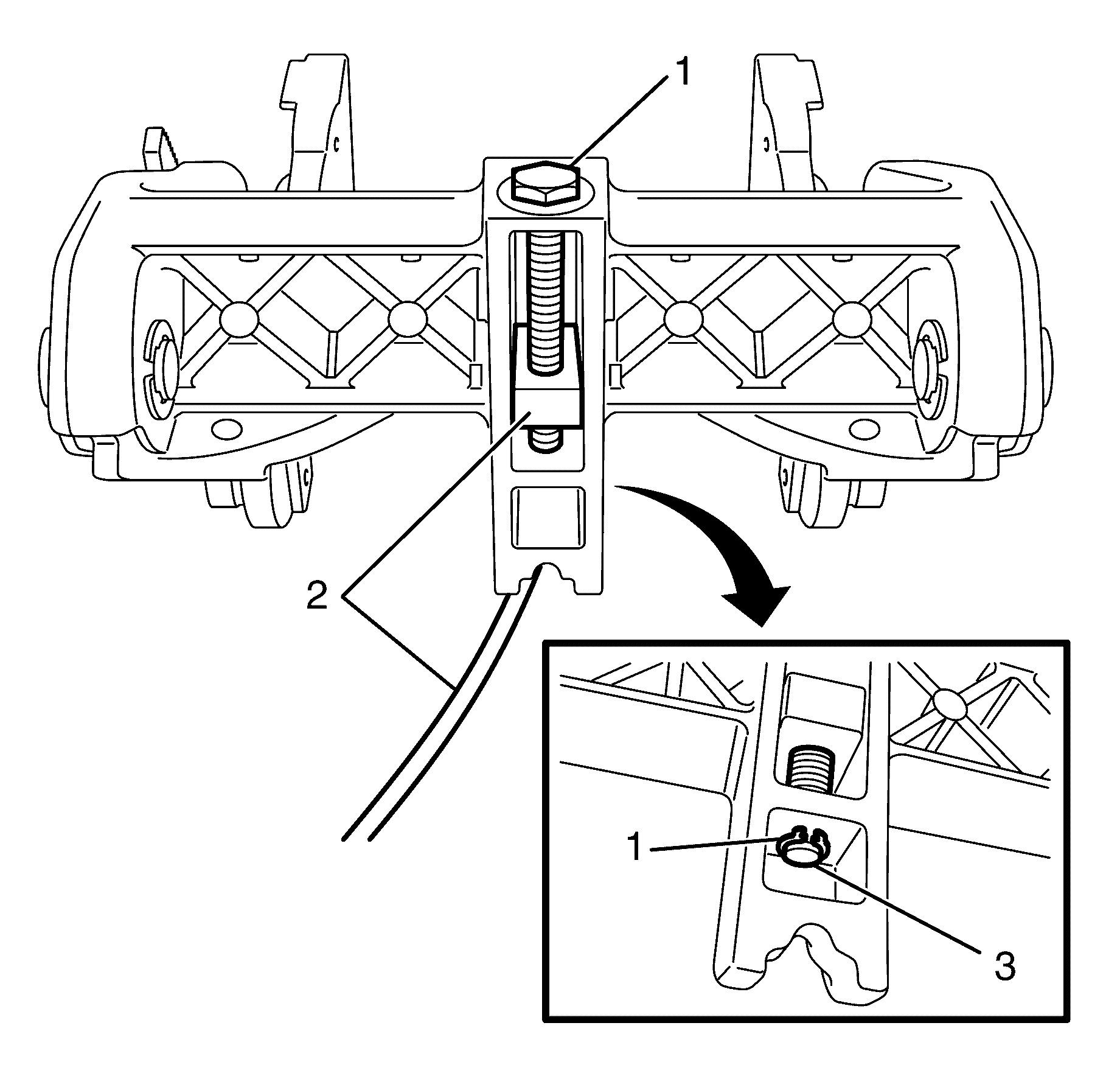
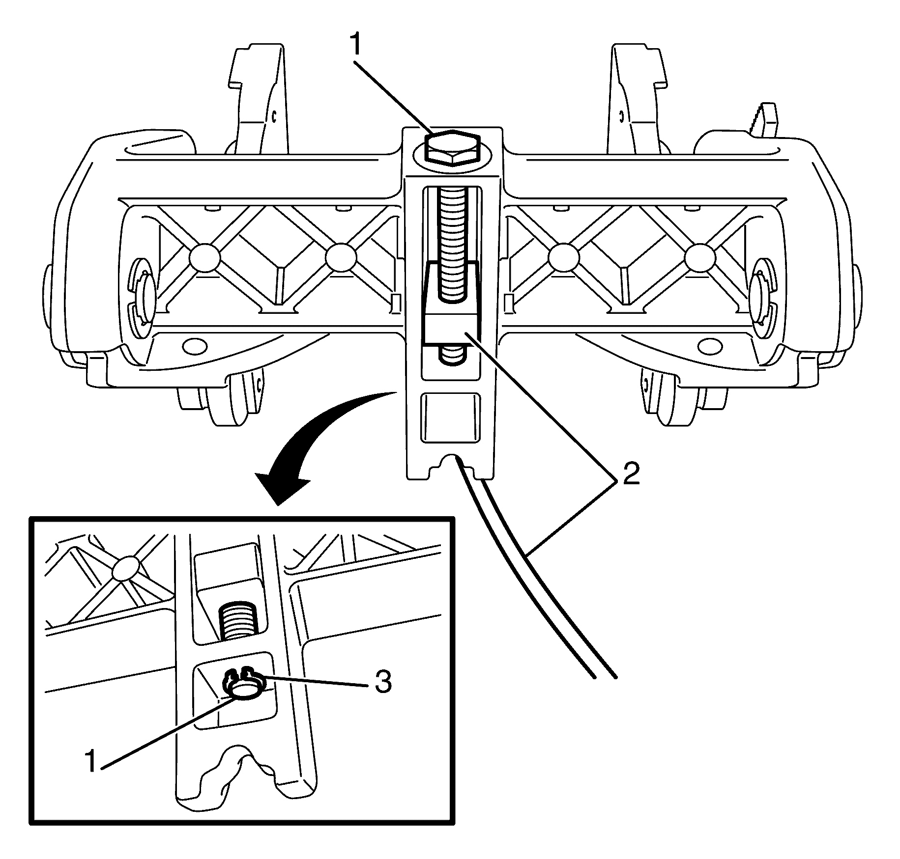
- Remove the park brake cable adjustment bolt to park brake assembly retaining circlip (1).
- Remove the park brake cable adjustment bolt (3).
- Remove the front park brake cable (2).
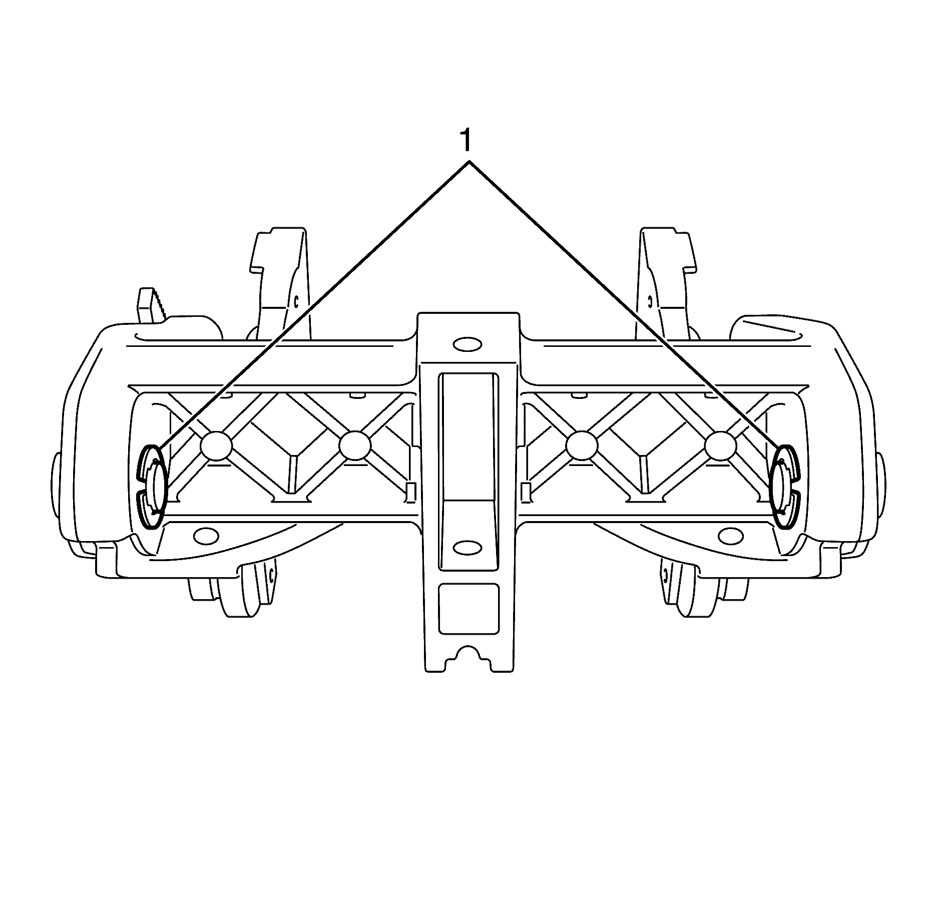
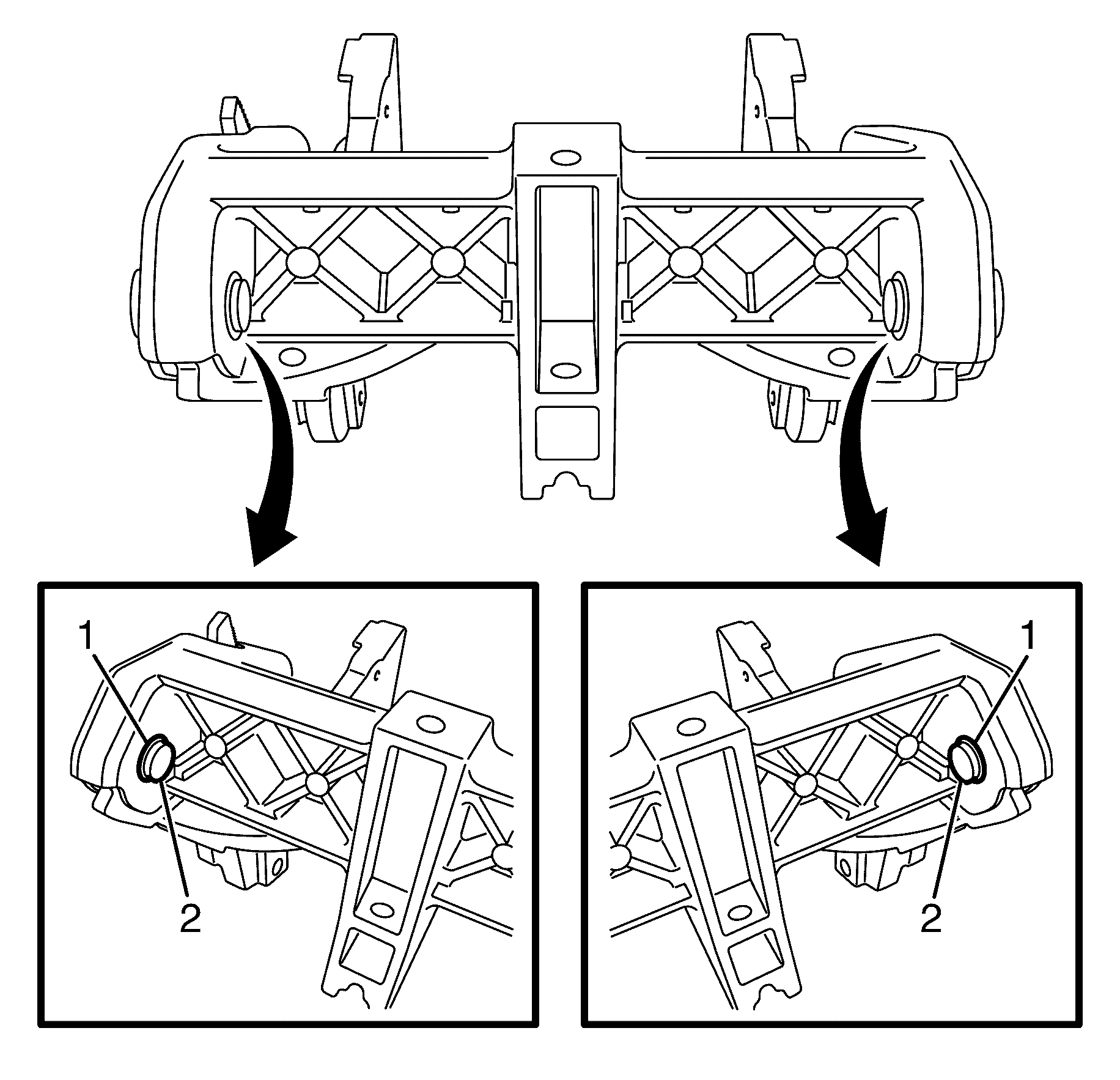
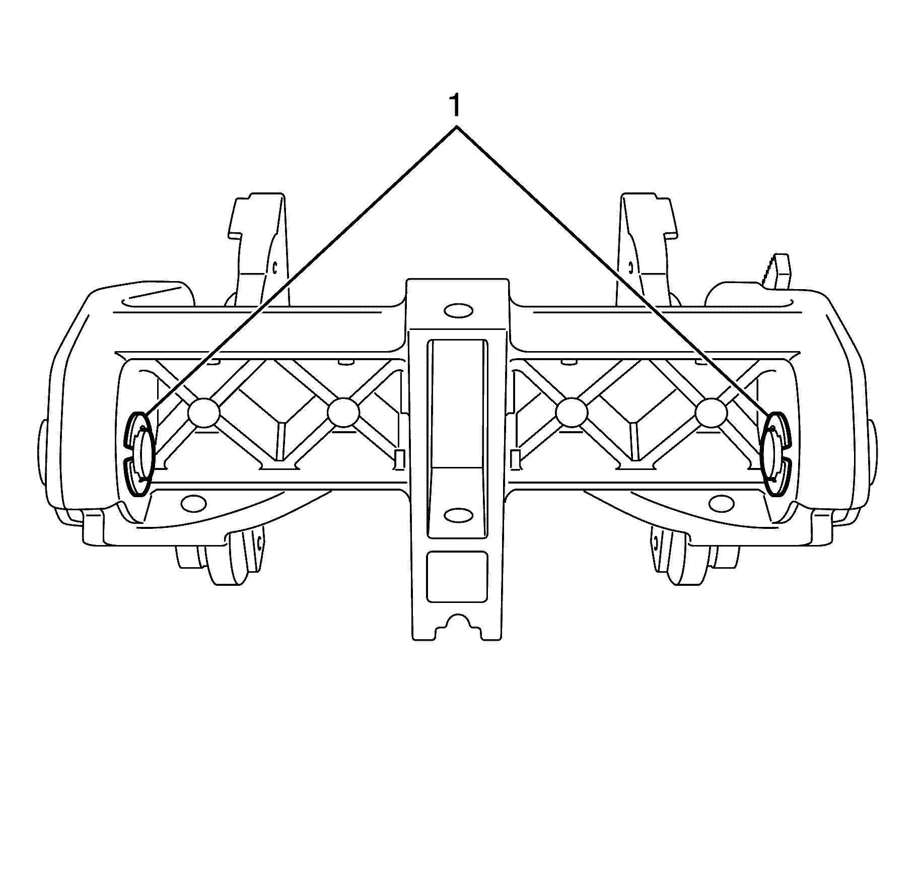
- Remove the pivot pin to park brake assembly retaining circlips (1).
- Remove the pivot pins (1) and bushes (2) from the park brake base.
- Separate the park brake lever assembly (1) from the park brake base (2).
Important: The park brake lever upper grip (1) is retained by clips and glue. Lift the park brake lever upper grip (1) upwards with your fingers to detach the clips from the park brake lever lower grip (5).
Important: Due to the glue holding them together, the park brake lever upper and lower grips will need replacing once disassembled.
Assembly Procedure
- Install the park brake lever assembly (1) to the park brake base (2).
- Install the pivot pins (1) and bushes (2) to the park brake base.
- Install the pivot pin to park brake assembly retaining circlips (3).
- Install the front park brake cable (2) into position.
- Install the park brake cable adjustment bolt (3).
- Install the park brake cable adjustment bolt to park brake assembly retaining circlip (1).
- Install a NEW park brake lever lower grip (4).
- Install the park brake lever to park brake lever lower grip retaining screws (3).
- Install the park brake lever spring and the park brake lever button (2).
- Attach the park brake lever cable (5) to the park brake lever button (2).
- Install a NEW park brake lever upper grip (1).
Important: The park brake lever upper grip (1) is retained by clips. Make sure all the clips are aligned with the park brake lever lower grip (4) and are engaged to avoid an induced rattle condition.
Important: This cable adjustment affects the release of the park brake, and could result in accidental release of the park brake.
Installation Procedure
- Install the park brake (3) to the rear floor air outlet duct (1).
- Install the rear floor air outlet duct to park brake assembly retaining screws (2).
- Install the rear floor air outlet duct to park brake assembly retaining screw (1).
- Install the front floor console cover assembly (1).
- Install the front floor console cover assembly to rear floor air outlet duct retaining screws (2).
- Install the rear front floor console cover assembly to rear floor air outlet duct retaining screws (1).
- Install the front floor console assembly. Refer to Front Floor Console Replacement .
- Adjust the park brake. Refer to Park Brake Adjustment .
Tighten
Tighten the bolt to 2 Nm (18 lb in).
Tighten
Tighten the bolt to 2 Nm (18 lb in).
Tighten
Tighten the bolt to 2 Nm (18 lb in).
Tighten
Tighten the bolt to 2 Nm (18 lb in).
Parking Brake Release Handle Assembly Replacement RHD
Removal Procedure
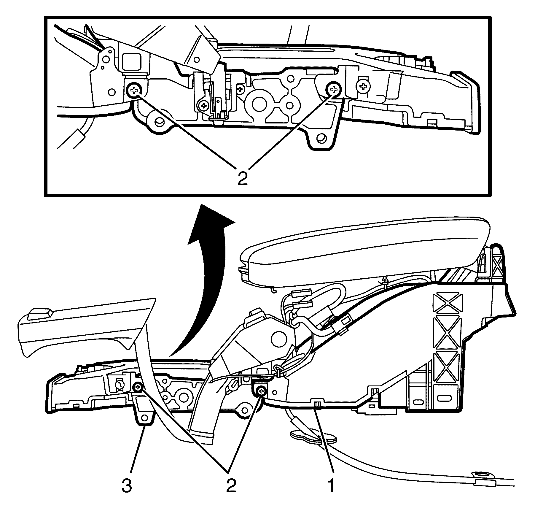
- Remove the front floor console assembly. Refer to Front Floor Console Replacement .
- Remove the rear front floor console cover assembly to rear floor air outlet duct retaining screws (1).
- Remove the front floor console cover assembly to rear floor air outlet duct retaining screws (2).
- Remove the front floor console cover assembly (1).
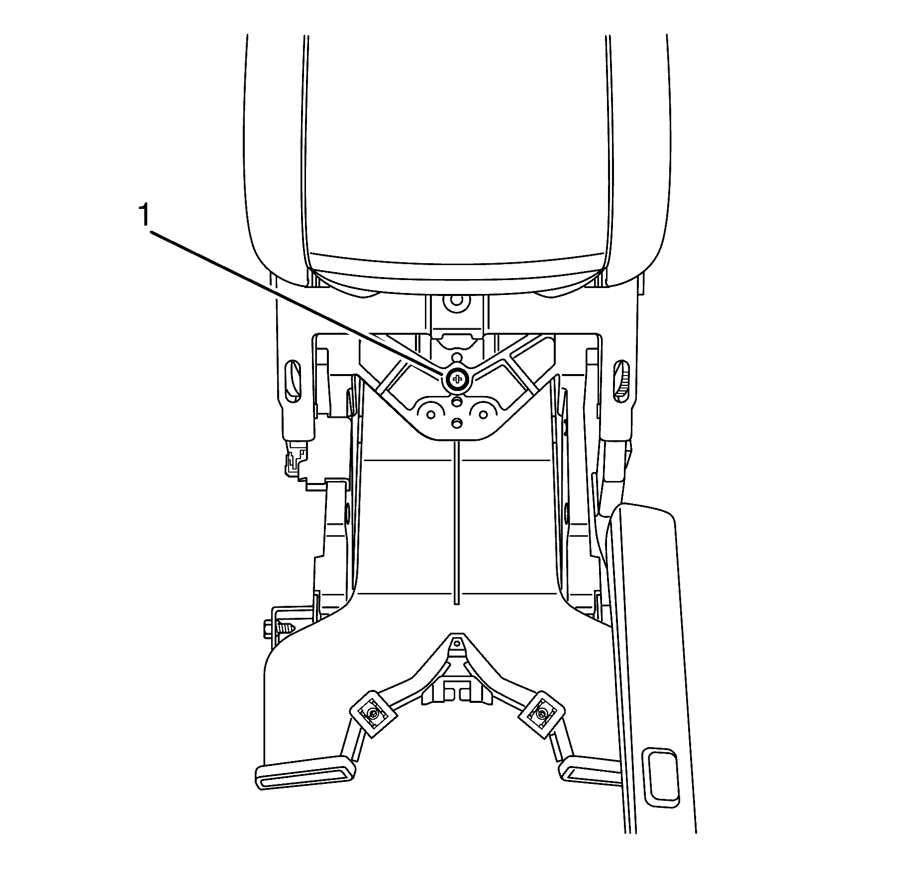
- Remove the rear floor air outlet duct to park brake assembly retaining screw (1).
- Remove the rear floor air outlet duct to park brake assembly retaining screw (2).
- Remove the park brake assembly (1) from the rear floor air outlet duct (3).
Disassembly Procedure
- Remove the park brake lever upper grip (1) and discard.
- Detach the park brake lever cable (4) from the park brake lever button (2).
- Remove the park brake lever button (2) and the park brake lever spring.
- Remove the park brake lever to park brake lever lower grip retaining screws (3).
- Remove the park brake lever lower grip (5) and discard.
- Remove the park brake cable adjustment bolt to park brake assembly retaining circlip (3).
- Remove the park brake cable adjustment bolt (1).
- Remove the front park brake cable (2).
- Remove the pivot pin to park brake assembly retaining circlips (1).
- Remove the pivot pins (1) and bushes (2) from the park brake base.
- Separate the park brake lever assembly (1) from the park brake base (2).

Important: The park brake lever upper grip (1) is retained by clips and glue. Lift the park brake lever upper grip (1) upwards with your fingers to detach the clips from the park brake lever lower grip (5).
Important: Due to the glue holding them together, the park brake lever upper and lower grips will need replacing once disassembled.
Assembly Procedure
- Install the park brake lever assembly (1) to the park brake base (2).
- Install the pivot pins (1) and bushes (2) to the park brake base.
- Install the pivot pin to park brake assembly retaining circlips (3).
- Install the front park brake cable (2) into position.
- Install the park brake cable adjustment bolt (1).
- Install the park brake cable adjustment bolt to park brake assembly retaining circlip (3).
- Install NEW park brake lever lower grip (5).
- Install the park brake lever to park brake lever lower grip retaining screws (3).
- Install the park brake lever spring and the park brake lever button (2).
- Attach NEW park brake lever cable (4) to the park brake lever button (2).
- Apply Glue to the six clips on the park brake lever lower grip (1).
- Apply Glue to the six clips on the park brake lever upper grip (1).
- Install the park brake lever upper grip (1).
Important: Make sure there is not preload on the button release cable, this cable adjustment affects the release of the park brake, and could result in accidental release of the park brake.
Important: Apply 3M Scotch-Weld Acrylic Structural Plastic Adhesive DP-8005 or super glue (Loctite 406) to the six clips to ensure the park brake lever upper grip is retained. Glue should be applied under the barb of clip.
Important: Apply 3M Scotch-Weld Acrylic Structural Plastic Adhesive DP-8005 or super glue (Loctite 406) to the six clips to ensure the park brake lever upper grip (1) is retained.
Important: The park brake lever upper grip (1) is retained by clips. Fit the top cover by clipping inboard side first, and rolling over. Hold top down tight while glue sets. Make sure all the clips are aligned with the park brake lever lower grip and are engaged to avoid an induced rattle condition.
Installation Procedure
- Install the park brake assembly (1) to the rear floor air outlet duct (3).
- Install the rear floor air outlet duct to park brake assembly retaining screw (2)
- Install the front floor console cover assembly (1).
- Install the front floor console cover assembly to rear floor air outlet duct retaining screws (2).
- Install the rear front floor console cover assembly to rear floor air outlet duct retaining screws (1).
- Install the front floor console assembly. Refer to Front Floor Console Replacement .
- Adjust the park brake. Refer to Park Brake Adjustment .
Tighten
Tighten the bolt to 2 Nm (18 lb in).
Tighten
Tighten the bolt to 2 Nm (18 lb in).
Tighten
Tighten the bolt to 2 Nm (18 lb in).
