For 1990-2009 cars only
Removal Procedure - Up to 17 Sept 2007
- Disable the SIR system. Refer to SIR Disabling and Enabling .
- Disconnect the battery ground cable from the battery. Refer to Battery Negative Cable Disconnection and Connection .
- Remove the instrument panel lower trim panel assembly. Refer to Instrument Panel Insulator Panel Replacement - Right Side .
- Remove the instrument panel lower trim panel retainer. Refer to Instrument Panel Retainer Replacement .
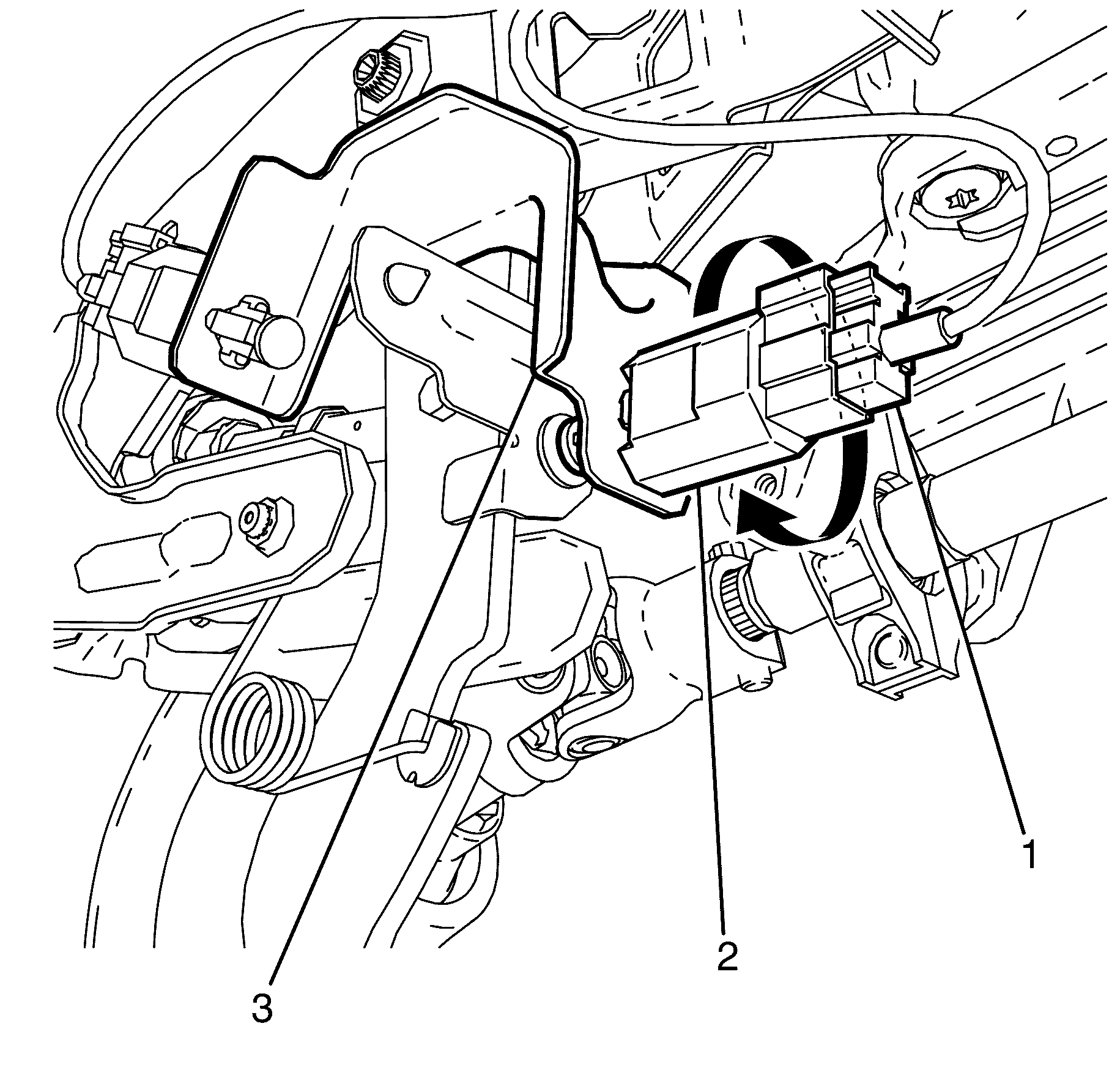
- Disconnect the clutch position switch electrical connector (1).
- Remove the clutch position switch (2).
Caution: Refer to Battery Disconnect Caution in the Preface section.

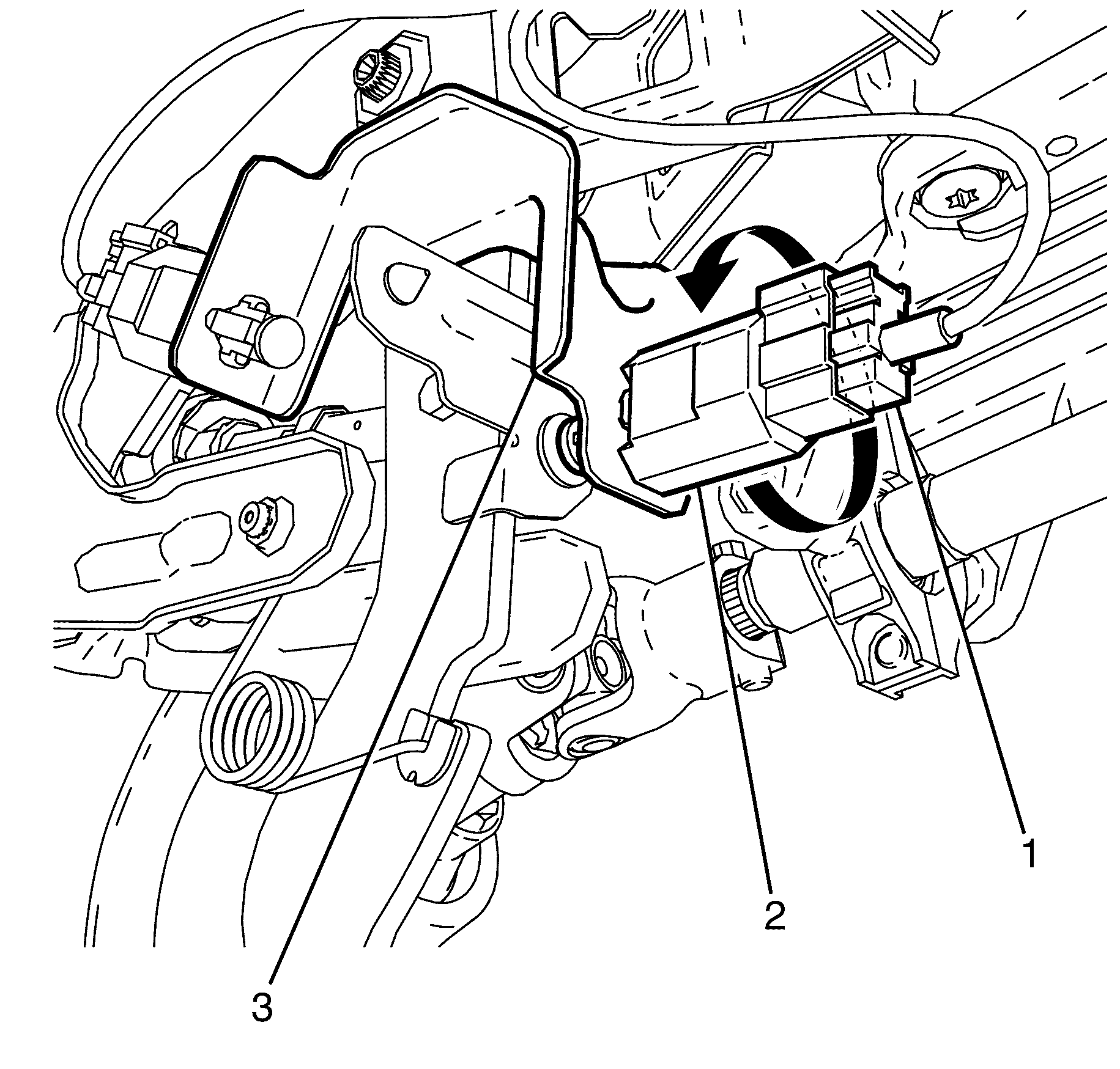
Important: Rotate the clutch position switch (2) clockwise a 1/4 turn, then pull to release from the clutch bracket (3).
Installation Procedure - Up to 17 Sept 2007
- Install the clutch position switch (2).
- Connect the clutch position switch electrical connector (1).
- Install the instrument panel lower trim panel retainer. Refer to Instrument Panel Retainer Replacement .
- Install the instrument panel lower trim panel assembly. Refer to Instrument Panel Insulator Panel Replacement - Right Side .
- Enable the SIR. Refer to SIR Disabling and Enabling .
- Connect the battery ground cable to the battery. Refer to Battery Negative Cable Disconnection and Connection .
- Road test vehicle for correct clutch operation.

Important: Rotate the clutch position switch (2) a 1/4 of a turn anti-clockwise to lock it into the clutch bracket (3).
Removal Procedure - From 17 Sept 2007
- Disconnect the battery ground cable from the battery. Refer to Battery Negative Cable Disconnection and Connection .
- Disable the SIR system. Refer to SIR Disabling and Enabling .
- Remove the instrument panel lower trim panel assembly. Refer to Instrument Panel Insulator Panel Replacement - Right Side .
- Remove the instrument panel lower trim panel retainer. Refer to Instrument Panel Retainer Replacement .
- Remove the clutch pedal assembly. Refer to Clutch Pedal Replacement .
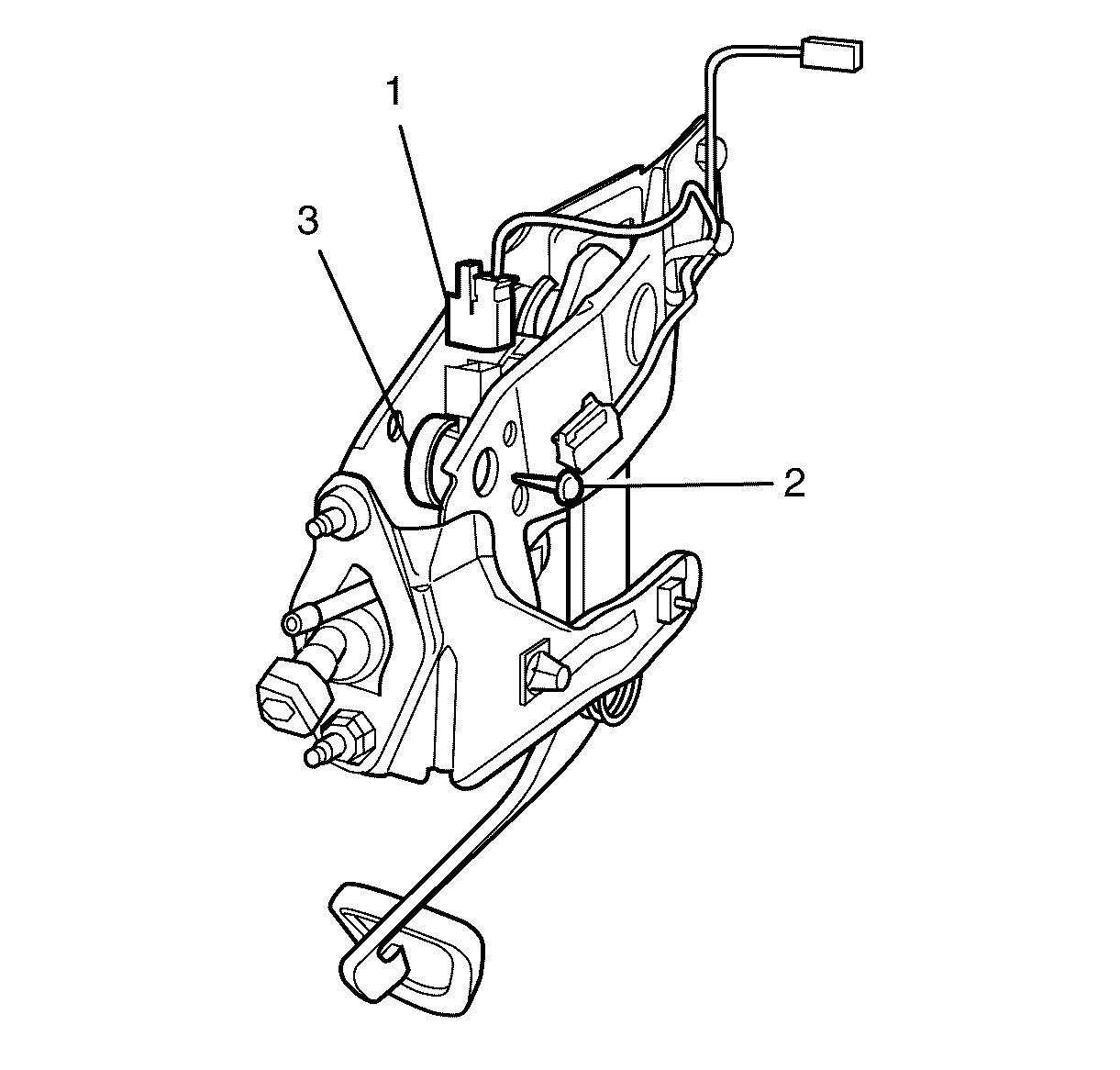
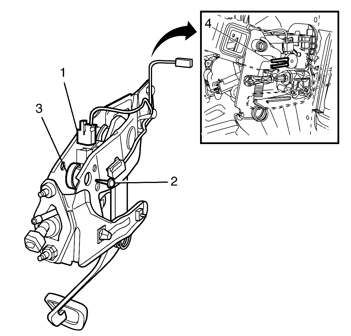
- Disconnect the clutch pedal position sensor electrical connector (1).
- Remove the clutch pedal assembly to clutch pedal position sensor retaining bolt (2).
- Remove the clutch pedal position sensor (3).
Caution: Refer to Battery Disconnect Caution in the Preface section.

Installation Procedure - From 17 Sept 2007
- Install the clutch pedal position sensor (3).
- Install the clutch pedal assembly to clutch pedal position sensor retaining bolt (2).
- Connect the clutch pedal position sensor electrical connector (1).
- Install the clutch pedal assembly. Refer to Clutch Pedal Replacement .
- Install the instrument panel lower trim panel retainer. Refer to Instrument Panel Retainer Replacement .
- Install the instrument panel lower trim panel assembly. Refer to Instrument Panel Insulator Panel Replacement - Right Side .
- Enable the SIR. Refer to SIR Disabling and Enabling .
- Connect the negative battery cable to the battery. Refer to Battery Negative Cable Disconnection and Connection .
- Road test vehicle for correct operation.

Important: Clutch pedal pin is located between the clutch pedal position sensor (3).
Tighten
Tighten the bolt to 13 N·m (115 lb in).
