For 1990-2009 cars only
Cylinder Head Replacement - Left Side RHD
Removal Procedure
- Disconnect the battery ground cable. Refer to Battery Negative Cable Disconnection and Connection.
- Remove the air inlet grille panel. Refer to Air Inlet Grille Panel Replacement.
- Remove the engine covers. Refer to Engine Cover Replacement.
- Remove the left camshaft cover. Refer to Camshaft Cover Replacement - Left Side.
- Remove the left bank secondary timing chain. Refer to Secondary Camshaft Drive Chain Replacement - Left Side.
- Remove the oil level indicator. Refer to Oil Level Indicator and Tube Replacement.
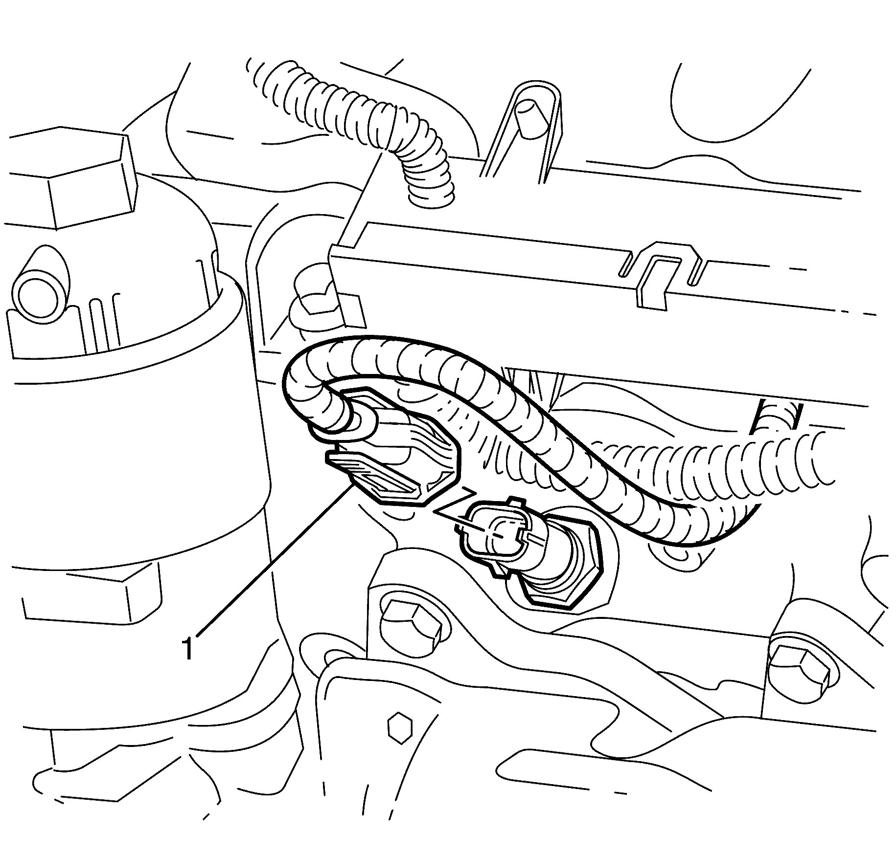
- Disconnect the coolant temperature sensor electrical connector (1).
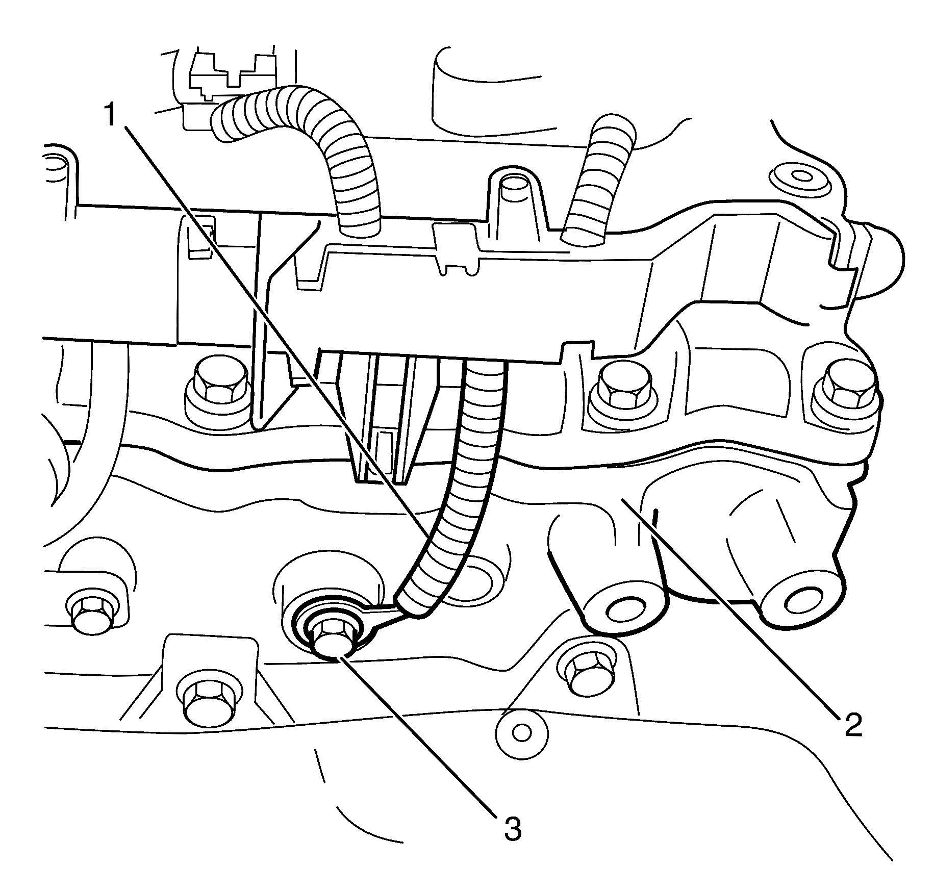
- Remove the wiring harness ground to cylinder head retaining bolt (3).
- Remove the wiring harness ground (1) from the cylinder head (2).
- Remove the upper intake manifold with the lower intake manifold. Refer to Lower Intake Manifold Replacement.
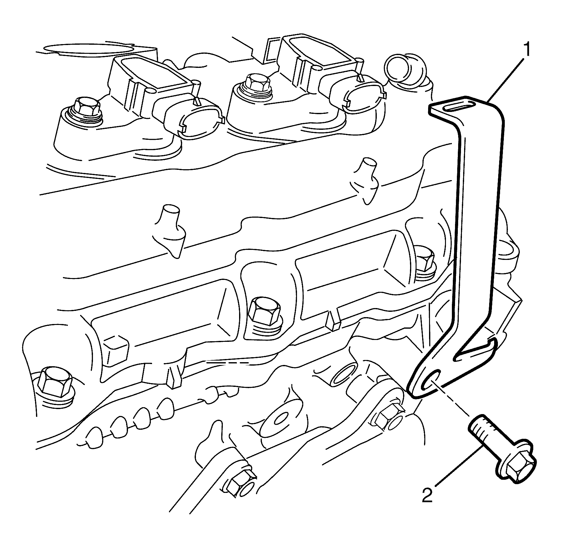
- Remove the left engine cover mounting bracket to cylinder head retaining bolt (2).
- Remove the left engine cover mounting bracket (2) from the cylinder head.
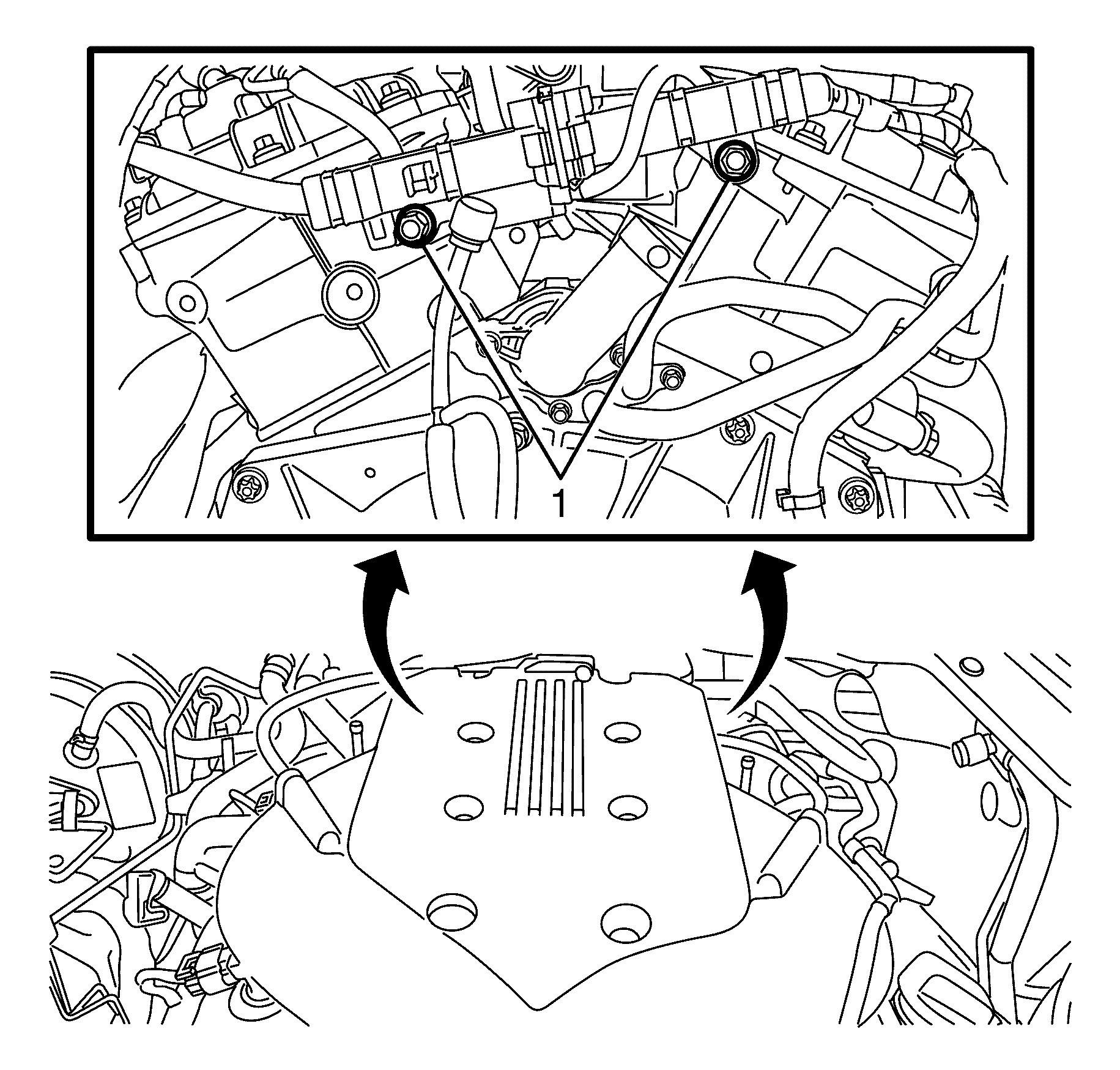
- Remove the engine wiring harness bracket to cylinder head retaining bolts (1).
- Remove the catalytic converter. Refer to Catalytic Converter Replacement - Left Side.
- Remove the oil filter adapter upper bolt (1).
- Remove the cylinder head with the exhaust manifold. Refer to Cylinder Head Removal - Left Side.
- Remove the cylinder head gasket (1).
- Clean and inspect the cylinder head and the cylinder block sealing surfaces. Refer to Cylinder Head Cleaning and Inspection and Engine Block Cleaning and Inspection.
- If necessary, perform the following steps:
Caution: Refer to Battery Disconnect Caution in the Preface section.
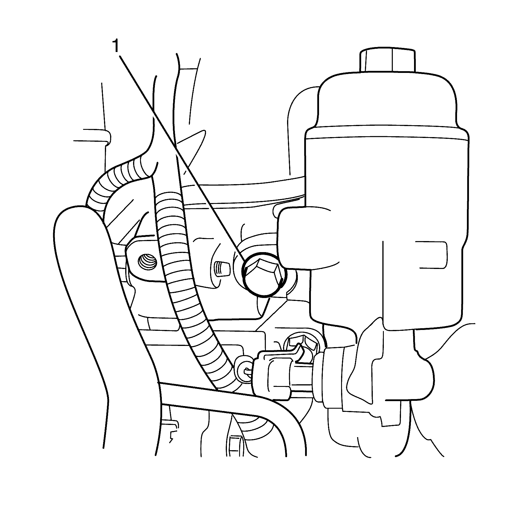
Important: DO NOT remove the oil filter adapter.
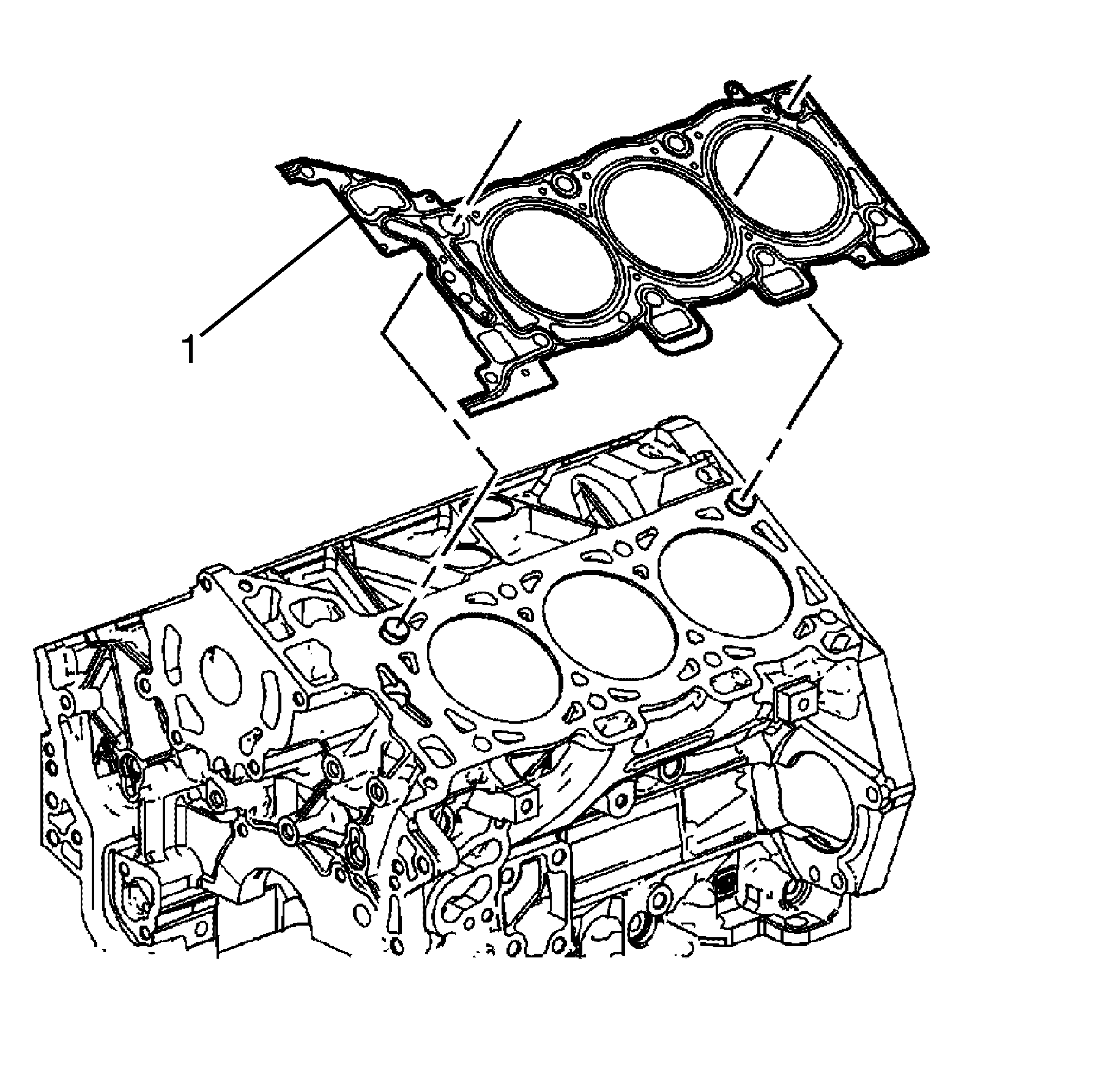
Important: Cylinder head gaskets must be discarded whenever the cylinder head has been removed from the cylinder block.
Discard the gasket.
| • | Remove the exhaust manifold from the cylinder head. Refer to Exhaust Manifold Removal - Left Side. |
| • | Disassemble the cylinder head. Refer to Cylinder Head Disassemble. |
Installation Procedure
- If necessary, perform the following steps:
- Install a NEW cylinder head gasket (1).
- Install the cylinder head with the exhaust manifold to the engine. Refer to Cylinder Head Installation - Left Side.
- Install the oil filter adapter upper retaining bolt (1).
- Install the catalytic converter to the exhaust manifold. Refer to Catalytic Converter Replacement - Left Side.
- Install the wiring harness bracket (2) to the rear of the cylinder head (3).
- Install the wiring harness bracket to cylinder head retaining bolts (1).
- Install the left engine cover mounting bracket (1) to cylinder head retaining bolt (2).
- Install the engine covers mounting bracket to cylinder head retaining bolt (2).
- Install the upper intake manifold with the lower intake manifold. Refer to Lower Intake Manifold Replacement.
- Install the wiring harness ground (1) to the cylinder head (2).
- Install the wiring harness ground to cylinder head retaining bolt (3).
- Connect the coolant temperature sensor electrical connector (1).
- Install the oil level indicator. Refer to Oil Level Indicator and Tube Replacement.
- Install the left bank secondary timing chain. Refer to Secondary Camshaft Drive Chain Replacement - Left Side.
- Install the left camshaft cover. Refer to Camshaft Cover Replacement - Left Side.
- Install the engine covers. Refer to Engine Cover Replacement.
- Install the air inlet grille panel. Refer to Air Inlet Grille Panel Replacement.
- Connect the battery ground cable. Refer to Battery Negative Cable Disconnection and Connection.
| • | Assemble the cylinder head. Refer to Cylinder Head Assemble. |
| • | Install the exhaust manifold to the cylinder head. Refer to Exhaust Manifold Installation - Left Side. |

Notice: Refer to Fastener Notice in the Preface section.

Tighten
Tighten the bolt to 65 N·m (48 lb in).

Tighten
Tighten the bolts to 10 N·m (89 lb in).

Tighten
Tighten the bolt to 35 N·m (26 lb in).

Tighten
Tighten the bolt to 10 N·m (89 lb in).

